Air blowout outlet structure for vehicle

a technology for air blowout and vehicle, which is applied in vehicle cleaning, vehicle heating/cooling devices, vehicle components, etc., can solve the problems of insufficient defogging effect, flow velocity drastically decrease, and area remained on a part of the window glass, etc., and achieve the effect of low pri

Inactive Publication Date: 2006-02-09
NIHON PLAST CO LTD
View PDF5 Cites 7 Cited by
  • Summary
  • Abstract
  • Description
  • Claims
  • Application Information

AI Technical Summary

Benefits of technology

[0022] With the configuration, since control for squeezing the air such that the squeezing level at the center side gradually increases compared with the two ends of the opening is easily performed, in addition, the second guide unit can be integrally formed with the first guide unit, the structure of air blowout outlet for a vehicle can be provided at a low price.

Problems solved by technology

However, since the air blown out from the air blowout outlet can not be extensively diffused only by providing the stationary blade at the air blowout outlet, there is a problem that sufficient defogging effects can not be obtained, for example, there is a problem that a fogged area is remained on a part of the window glass.
However, in the defroster structure described in the above Japanese Patent Provisional Publication, since the blowout nozzle for guiding the air, which is to be blown to the inner surface of the front window glass, to the air blowout outlet is formed in a way that the dimension gradually increases in the vehicle width direction with approaching the side of the air blowout outlet, there is a problem that, in the air flown from the main duct into the blowout nozzle, flow velocity drastically decreases with approaching the air blowout outlet, as a result the air blown out from the air blowout outlet to the inner surface of the front window glass does not sufficiently reach to, for example, two upper corners of the front window glass distant from the air blowout outlet, or even if it reaches there, since the flow rate is small, flogging can not be prevented at the corner portions.
In addition, there is a problem that since a dimension of the air blowout outlet needs to be increased in accordance with the blowout nozzle of which the dimension gradually increases in the vehicle width direction toward the air blowout outlet, an opening area of the air blowout outlet becomes large, thereby appearance of an instrument panel becomes bad, and when the main duct, side duct, and blowout nozzle are formed with injection molding using resin, a separable mold is necessary, resulting in increase in mold cost.

Method used


Image

  • Air blowout outlet structure for vehicle
  • Air blowout outlet structure for vehicle
  • Air blowout outlet structure for vehicle

Examples


Embodiment Construction

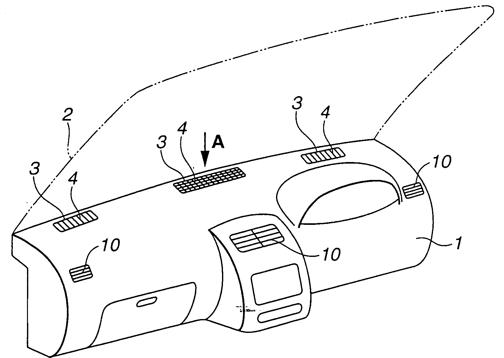
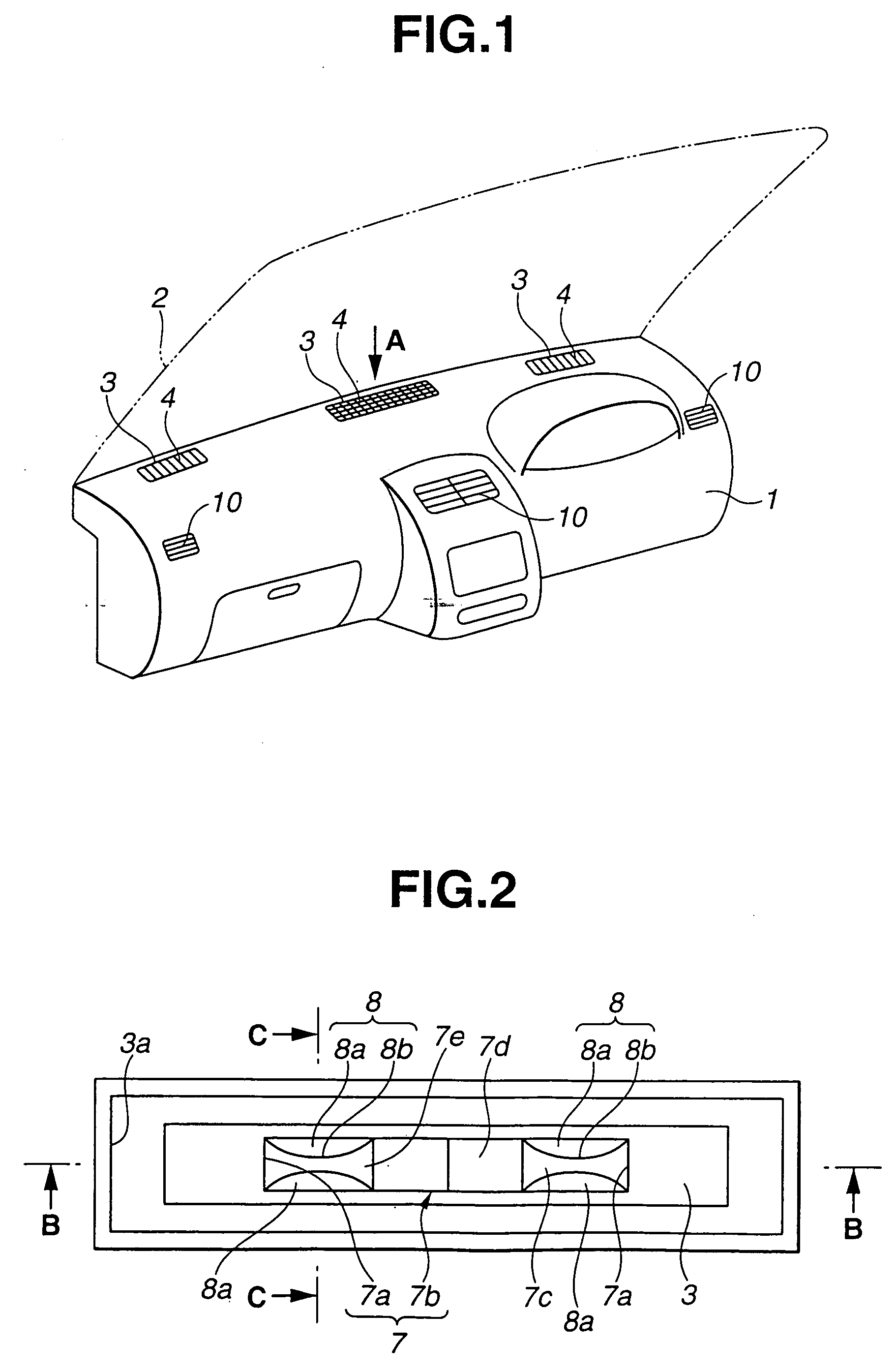
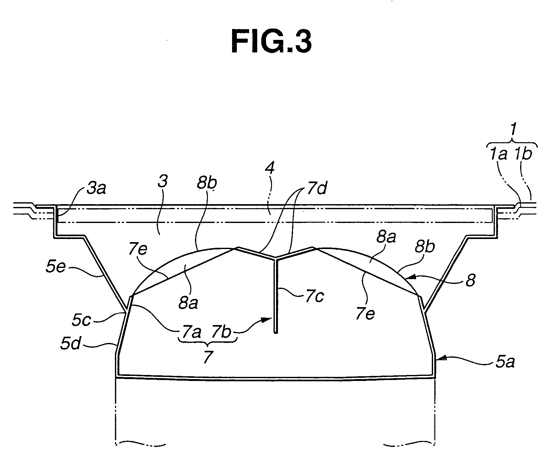
[0032] Discussion will be made in detail on an embodiment of the present invention where the invention is applied to an air blowout outlet structure for a defroster arranged to blow out air to the inner surface of a front window glass of an automotive vehicle, with reference to FIG. 1 to FIG. 7 of the drawings. In The drawings, FIG. 1 is a perspective view of an instrument panel using a structure of the air blowout outlet for a vehicle according to an embodiment of the invention; FIG. 2 is an enlarged diagrammatic view as viewed from the direction A of FIG. 1; FIG. 3 is a cross sectional view taken along the line B-B of FIG. 2; FIG. 4 is a cross sectional view taken along the line C-C of FIG. 2; FIG. 5 is a perspective view of air blowout members forming the structure of the air blowout outlet for a vehicle according to the embodiment of the invention; FIG. 6 is an exploded perspective view of the air blowout members forming the structure of air blowout outlet for a vehicle accordin...


PUM


Abstract

A structure of an air blowout outlet for a vehicle, includes a case having an air inlet through which air is supplied. A pair of first wall sections extend in a longitudinal direction of the case. A pair of second wall sections are provided in such a manner that each second wall section connects end portions of the first wall sections. The first wall sections and the second wall sections define an air outlet through which air supplied from the air inlet is blown out. A first guide is formed at an inner surface of the second wall sections to extend in a longitudinal direction of the case so as to squeeze air introduced from the air inlet. Additionally, a second guide is formed at an inner surface of the first wall sections. A central portion of the second guide in the longitudinal direction of the case extends larger than an end portion of the second guide in the longitudinal direction of the case so that the central portion squeezes air larger than the end portion.

Description

BACKGROUND OF THE INVENTION [0001] 1. Field of the Invention [0002] The present invention relates to improvements in a structure of an air blowout outlet for a vehicle, which can blow out air to an inner surface of a window glass such as a front window glass or an interior of a passenger compartment uniformly and extensively. [0003] 2. Description of the Prior Art [0004] In a vehicle such as automobile, air blowout outlets are opened at appropriate places in a interior of a passenger compartment, and air conditioned by an air conditioner is blown out from the air blowout outlets to the interior of a passenger compartment. [0005] The air blowout outlets include an air blowout outlet for keeping environment of the interior of a passenger compartment comfortable by blowing out the air conditioned by the air conditioner to the interior of a passenger compartment, in addition, an air blowout outlet for defroster for preventing fogging of the window glass with steam by blowing dry air fro...

Claims


Application Information

Patent Timeline
Patent Type & Authority Applications(United States)
IPC IPC(8): B60S1/54B60H1/34
CPCB60H1/3407
Inventor KAMANO, YOSHIFUMIISHIKAWA, HIROYUKINAKAMURA, TATSUHIKO
Owner NIHON PLAST CO LTD
Why Eureka
Try Eureka