Method and system of remote diagnostic, control and information collection using a dynamic linked library of multiple formats and multiple protocols with restriction on protocol
What is AI technical title?
AI technical title is built by PatSnap AI team. It summarizes the technical point description of the patent document.
a dynamic linking and information collection technology, applied in the field of methods and systems of remote diagnostics, control and information collection, can solve problems such as warning conditions and error conditions
Inactive Publication Date: 2006-02-09
RICOH KK
View PDF50 Cites 35 Cited by
Summary
Abstract
Description
Claims
Application Information
AI Technical Summary
This helps you quickly interpret patents by identifying the three key elements:
Problems solved by technology
Method used
Benefits of technology
Benefits of technology
The present invention provides a system for monitoring events of a target application of an application unit and communicating the data obtained by monitoring to a remote party. The system can communicate data in various formats and protocols, allowing for easy analysis and data verification. The system can also efficiently communicate the monitored event information to a transmission unit and meet the requirement on the second parameter. The data obtained by monitoring events of a target application can be collected, logged, and communicated to a desired location using store-and-forward or direct connection protocols. The technical effects of the invention include improved monitoring and analysis of events, reduced costs associated with communication, and efficient data communication.
Problems solved by technology
Some events may be caused by abnormal conditions such as paper jam in the copiers.
Some error conditions and warning conditions may be caused by errors in the software installed in the target appliances and devices.
Method used
Image
Click on the blue label to locate the original text in one second.
Reading with bidirectional positioning of images and text.
Examples
Embodiment Construction
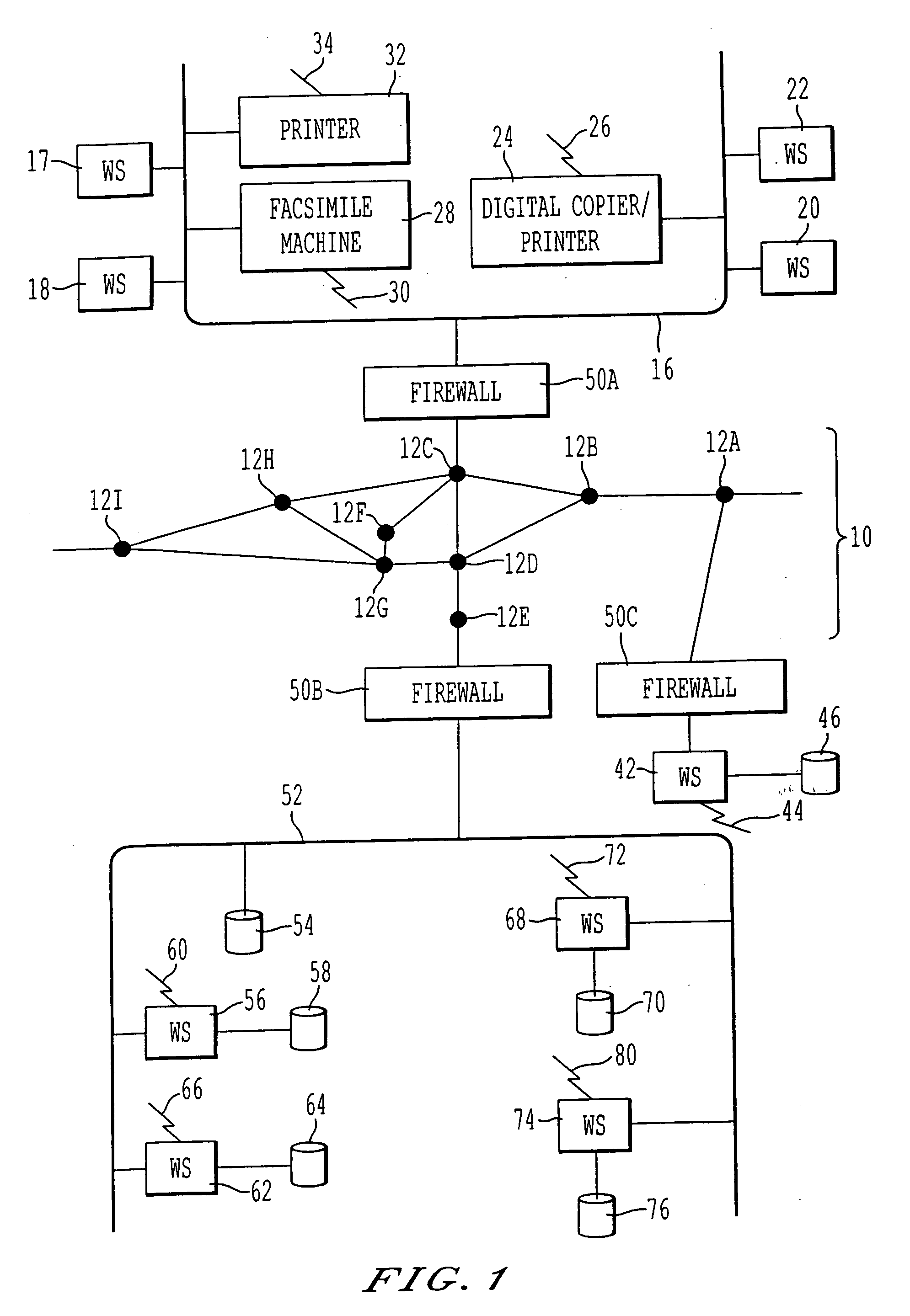
[0049] Referring now to the drawings, wherein like reference numerals designate identical or corresponding parts throughout the several views, FIG. 1 illustrates (1) various machines and (2) computers for monitoring, diagnosing and controlling the operation of the machines. In FIG. 1, there is a first network 16, such as a Local Area Network (LAN) connected to computer workstations 17, 18, 20 and 22. The workstations can be any type of computers including IBM Personal Computer compatible devices, Unix-based computers, or Apple Macintoshes. Also connected to the network 16 are (1) a digital image forming apparatus 24, (2) a facsimilemachine 28, and (3) a printer 32. As would be appreciated by one of ordinary skill in the art, two or more of the components of the digital image forming apparatus 24 and the facsimilemachine 28 can be combined into a unified “image forming apparatus.” The devices 24, 28 and 32 and the workstations 17, 18, 20 and 22 are referred to as machines or monito...
PUM
Abstract
A method, system and computer program product for (1) collecting information from a remote application unit and / or (2) diagnosing or controlling the remote application unit. By utilizing a shareable computer code device (e.g., a dynamic linked library), a new application can utilize tested, proven code without having to reproduce existing functionality. Moreover, by supporting multiple data formats and / or multiple communication protocols, a computer code device increases the likelihood that a supported format and / or protocol will be either receivable or understandable by a receiver.
Description
CROSS-REFERENCE TO RELATED APPLICATIONS [0001] The present application, attorney docket number 5244-0125-2, is related to the following U.S. applications and patents: Ser. No. 09 / 440,692 of 1999-Nov.-16; Ser. No. 09 / 440,647 of 1999-Nov.-16; Ser. No. 09 / 440,646 of 1999-Nov.-16; Ser. No. 09 / 440,693 of 1999-Nov.-16; Ser. No. 09 / 440,645 of 1999-Nov.-16; Ser. No. 09 / 408,443 of 1999-Sep.-29; Ser. No. 09 / 407,769 of 1999-Sep.-29; Ser. No. 09 / 393,677 of 1999-Sep.-10; Ser. No. 09 / 311,148 of 1999-May-13; Ser. No. 09 / 192,583 of 1998-Nov.-17; Ser. No. 09 / 190,460 of 1998-Nov.-13; Ser. No. 08 / 883,492 of 1997-Jun.-26; Ser. No. 09 / 108,705 of 1998-Jul.-01; Ser. No. 09 / 107,989 of 1998-Jul.-01; Ser. No. 08 / 997,482 of 1997-Dec.-23; Ser. No. 08 / 997,705 of 1997-Dec.-23; Ser. No. 08 / 738,659 of 1996-Oct.-30; Ser. No. 08 / 738,461 of 1996-Oct.-30; Ser. No. 09 / 457,669 of 1999-Dec.-09; Ser. No. 08 / 916,009 of 1997-Aug.-21; Ser. No. 07 / 902,462 of 1992-Jun.-19; Ser. No. 07 / 549,278 of 1990-Jul.-06; Pat. Nos. 5,908,4...
Claims
Application Information
Patent Timeline
Application Date:The date an application was filed.
Publication Date:The date a patent or application was officially published.
First Publication Date:The earliest publication date of a patent with the same application number.
Issue Date:Publication date of the patent grant document.
PCT Entry Date:The Entry date of PCT National Phase.
Estimated Expiry Date:The statutory expiry date of a patent right according to the Patent Law, and it is the longest term of protection that the patent right can achieve without the termination of the patent right due to other reasons(Term extension factor has been taken into account ).
Invalid Date:Actual expiry date is based on effective date or publication date of legal transaction data of invalid patent.
Patent Type & AuthorityApplications(United States)

