
Casing assembly for burglar alarms

a technology for burglar alarms and casings, which is applied in the direction of electrical apparatus casings/cabinets/drawers, anti-theft devices, instruments, etc., can solve the problems of easy opening or damage of screw holes, high labor cost and material cost, and inconvenient replacement of batteries for burglar alarms, etc., to reduce the assembling cost, simple and quick assembly, and not easily damaged by external forces

Inactive Publication Date: 2006-02-16
CHEN YI CHEN
View PDF5 Cites 12 Cited by
  • Summary
  • Abstract
  • Description
  • Claims
  • Application Information

AI Technical Summary

Benefits of technology

[0010] Therefore it is the primary objective of the present invention to provide an improved casing assembly for burglar alarms, which uses corresponding coupling components for the connection without using additional coupling devices to provide a simple and quick assembly and also features the advantage of lowering the assembling cost. In addition, the close connections between components can effectively prevent the burglar alarm from being damaged by external forces.
[0011] To achieve the foregoing objective, the present invention comprises an upper casing, a chassis and a front panel, wherein a circuit board and a speaker are included in the upper casing and the chassis, and the front panel is covered onto the exterior of the upper casing and locked with the chassis integrally by a lock. An embedding plate extended from the bottom edge along the periphery of the front panel is coupled tightly with a groove extended around the chassis, and thus the burglar alarm cannot be damaged easily by external forces.
[0012] Another objective of the present invention is to install two interconnected hollow pillars with unequal diameters, and these two hollow pillars are disposed on the upper casing; a through hole disposed on the chassis at a position corresponding to the hollow pillar having a larger diameter, such that a steel rope having a metal head is passed through the through hole of the chassis into the hollow pillar having a larger diameter, and then coupled with the hollow pillar having a smaller diameter. The front panel covers the hollow pillars such that the steel rope will not fall out and the burglar alarm can be tied with the handle or a steering wheel for protecting the desired object.
[0013] A further objective of the present invention is to build a corresponding slot on the chassis, the hollow pillars and the front panel, so that an electric wire can be connected to the magnetic spring switch from the outside through the slots, which gives another way of using the burglar alarm such that the casing assembly can fit different types of burglar alarms and achieve the effect of saving the mold manufacturing cost.

Problems solved by technology

Therefore, the labor cost and material cost will be very high.
When a burglar alarm incorporating screws for its fixture is in use, special attention about the positions of the hidden screws must be paid, or else the screw holes will be exposed and can be opened or damaged easily.
The positions of all screw holes of a burglar alarm incorporating screws for its fixture are located at the bottom, and such arrangement makes the change of battery very inconvenient for a burglar alarm that is installed onto a wall.
Therefore, the architecture of a burglar alarm that incorporates screws for its fixture incurs higher labor cost and material cost for securing the screws and has the shortcomings of having an easily damaged and inconvenient screw hole and a limitation on the screw positions that does not allow a steel rope to pass through or fix a steel rope onto a wall by suspension at the same time.

Method used


Image

  • Casing assembly for burglar alarms
  • Casing assembly for burglar alarms
  • Casing assembly for burglar alarms

Examples


Embodiment Construction

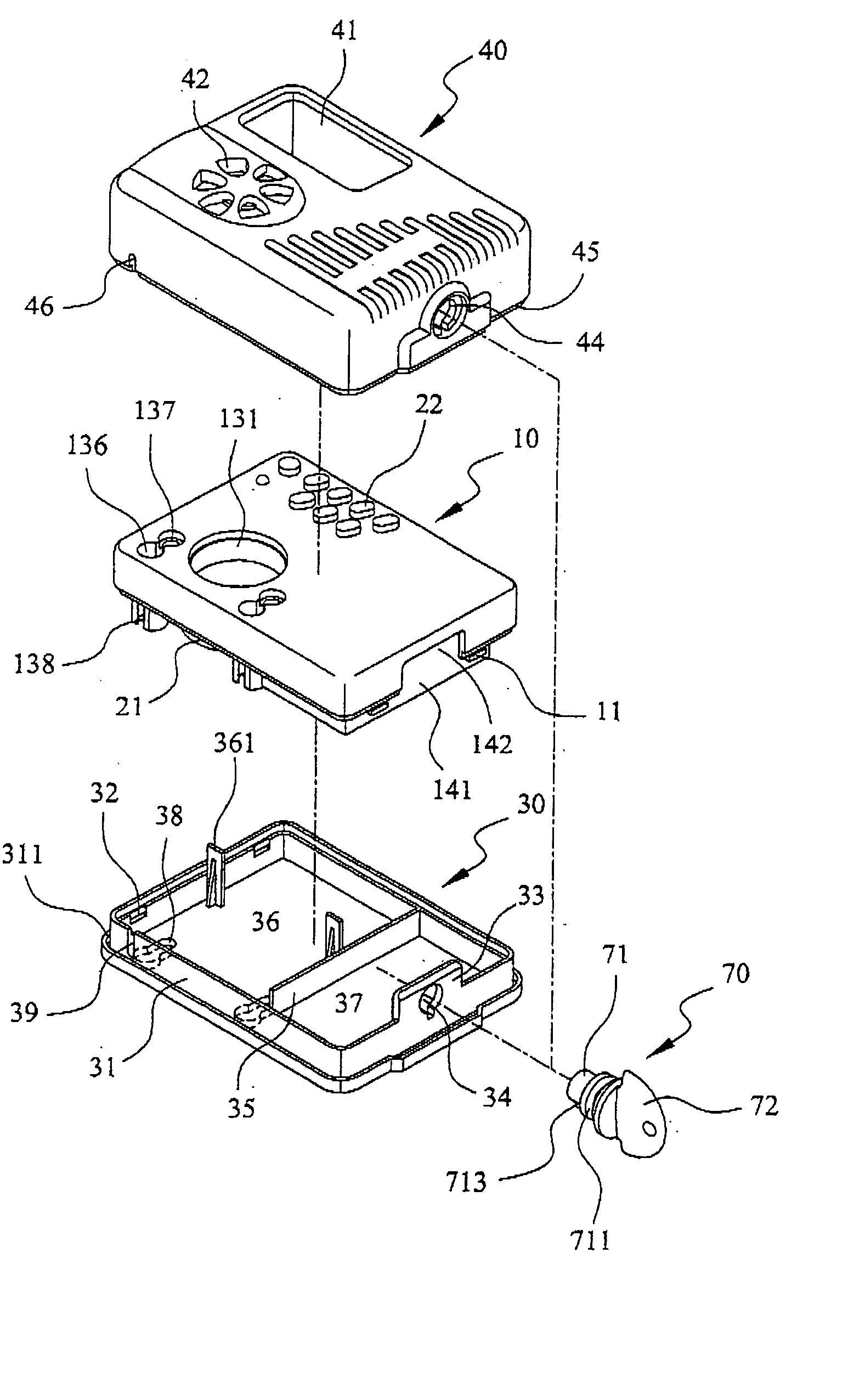
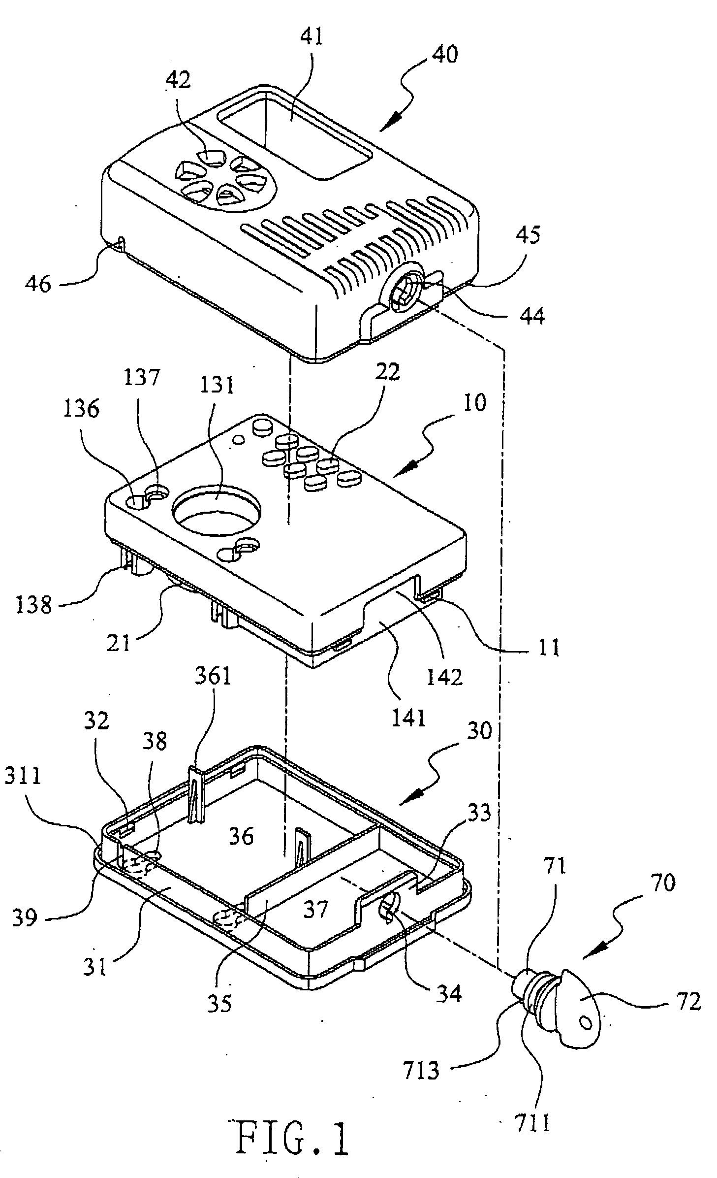
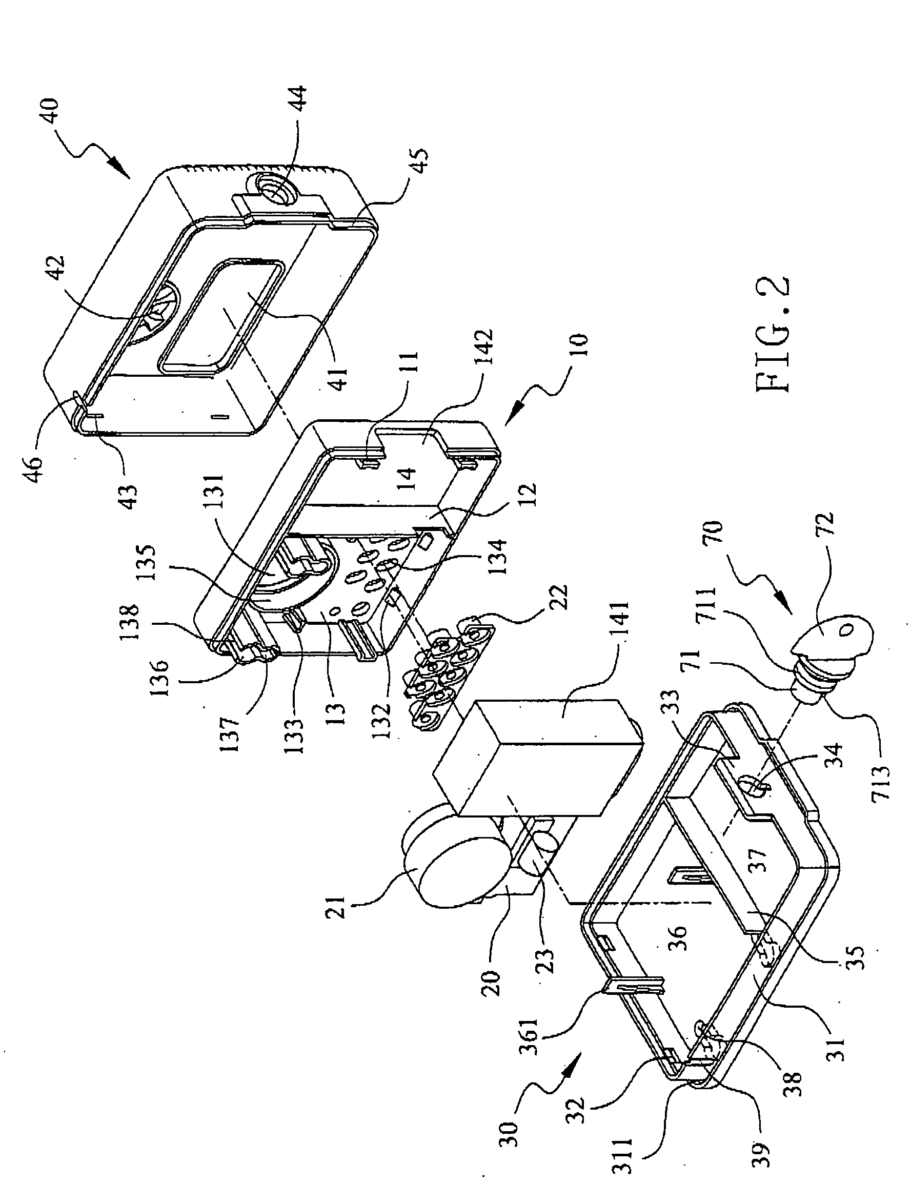
[0023] Please refer to FIGS. 1 and 2 for exploded views at two different angles of the casing assembly according to the present invention. The casing assembly for a burglar alarm comprises the following elements:

[0024] An upper casing 10 defines an embedded accommodating space and has at least one latch pillar 11 individually disposed on both sides of the upper casing 10, and a partition board 12 divides the accommodating space into two sections: a circuit board accommodating section 13 and a battery accommodating section 14; wherein the circuit board accommodating section 13 comprises a latch set for retaining a circuit board 20 and a hollow cavity 131 for retaining a speaker 21, and the latch set is comprised of at least one press latch bracket 132 disposed at the internal edge of the casing of the upper casing 10 and at least one limit plate 133 disposed at a distance equal to the width of the circuit board 20 from the internal edge of the upper casing 10, and a plurality of pre...


PUM


Abstract

The present invention discloses an improved casing assembly for burglar alarm, and the casing comprises an upper casing, a chassis and a front panel; wherein a circuit board and a speaker are included in the upper casing and the chassis and the front panel is covered on the exterior of the upper casing and locked with the chassis by a lock as a whole. The assembly of the forgoing components is connected by the corresponding coupling components on the assembly and thus does not require additional coupling device, which makes the assembly much simpler and quicker and has the advantages of lowering the manufacturing and labor costs. In the meantime, the printed circuit according to the present invention is coupled to a vibration switch or magnetic spring switch as a sensor triggering source for acting as a trigger of the burglar alarm for motor vehicles, portable objects, displayed items, doors and windows, security or display windows. All these burglar alarms can share the same casing and thus can save the cost for manufacturing the molds. The casing can go with a rope having a metal head for passing through, suspending at or fixing onto a wall to give an excellent antitheft protection effect.

Description

BACKGROUND OF THE INVENTION [0001] 1. Field of the Invention [0002] The present invention relates to an improved casing assembly for burglar alarms, more particularly to a design of casing assembly that does not require screws for its fixture and has a close assembly which prevents break-in by external forces, and such design fits the installation for motor vehicles, portable objects, displayed items, windows and doors, security or display windows by passing, suspending or fixing the casing assembly onto a wall. [0003] 2. Description of the Related Art [0004] A burglar alarm is a device for generating a shrill noise to scare away a burglar or identify an unauthorized intrusion. To achieve these objectives, a burglar alarm primarily relies on the precise of its detection for a slight movement and prevents the burglar alarm from being damaged or disabled by external forces. Regardless the detection methods, most of the current burglar alarms use screws or similar components to assembl...

Claims


Application Information

Patent Timeline
IPC IPC(8): G08B23/00
CPCB60R25/10H05K5/0221B60R25/1001
Inventor CHEN, YI-CHEN
Owner CHEN YI CHEN
Learn More