Interlabial pad

a technology for interlabial pads and pads, applied in the field of interlabial pads, can solve the problems of difficult opening of labia minora pudenda near the vestibule floor, and achieve the effect of reducing the likelihood of falling off of the pad

Inactive Publication Date: 2006-02-16
UNI CHARM CORP
View PDF7 Cites 14 Cited by
  • Summary
  • Abstract
  • Description
  • Claims
  • Application Information

AI Technical Summary

Benefits of technology

[0014] The inventors have made an extensive effort to solve the above-mentioned problems. As a result, the inventors have completed the invention based on the fact that making the compression repulsive force from the portion contacting near the vestibular floor greater than the compression repulsive force from the portion contacting near the anterior ends of the labia minora pudenda allows a manufacturer to provide an interlabial pad capable of reducing the likelihood of falling-off of the pad and leakage of bodily exudates. More specifically, the invention provides the followings.

Problems solved by technology

Accordingly, portions near the anterior ends of the labia minora pudenda largely open, however, the labia minora pudenda near the vestibule floor are difficult to open because the labia minora pudenda at the above-mentioned point are pushed inside by the right and left labia majora pudenda located outside the labia minora pudenda.

Method used


Image

  • Interlabial pad
  • Interlabial pad
  • Interlabial pad

Examples


first embodiment

[0065] [Overall Configuration of an Interlabial Pad]

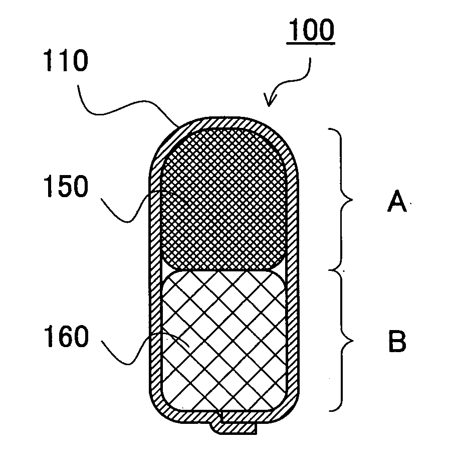
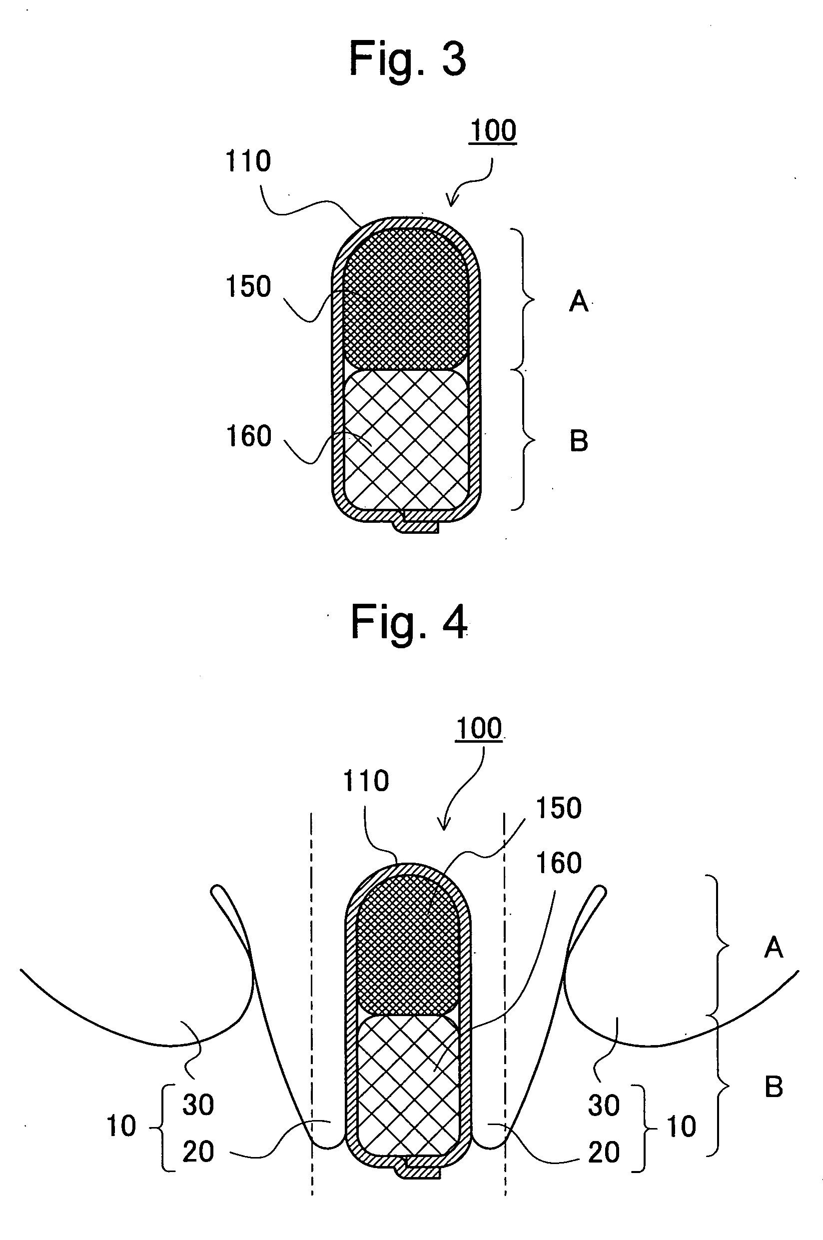
[0066]FIG. 3 is a cross-sectional view of an interlabial pad 100 according to the present embodiment, taken along a plane perpendicular to the central longitudinal axis of the pad. As shown in FIG. 3, the interlabial pad 100 according to the invention comprises an absorbent body covered with a topsheet 110, the first portion “A” and the second portion “B”. Further, a part of an absorbent body 150 of high fiber density is disposed in the first portion “A” and another part of an absorbent body 160 of low fiber density is disposed in the second portion “B”. The topsheet 110 is positioned on wearer's body side during use of the pad (hereinafter, referred to simply as “during use”) and pervious to body exudates of a wearer.

[0067]FIG. 4 is a diagram showing the used state of the interlabial pad 100 according to the invention. Although during use, larger interlabial pressure is applied to the first portion “A”, compression repulsive forc...

second embodiment

[0094] An interlabial pad 200 according to this embodiment is characterized in that an absorbent body 250 in the first portion “A” is thicker than the absorbent body 250 in the second portion “B”. The remaining configuration of the embodiment is similar to that of the first embodiment. FIG. 6 is a cross sectional view of the interlabial pad 200, taken along a plane perpendicular to the central longitudinal axis of the pad. The thickness of the absorbent body 250 in the first portion “A” is preferably 1.2 to 10 times the thickness of the absorbent body 250 in the second portion “B”. In more detail, the thickness of the absorbent body 250 in the first portion “A” is preferably in the range of 2 mm to 20 mm and more preferably in the range of 3 mm to 15 mm. Further, the thickness of the absorbent body 250 in the second portion “B” is preferably in the range of 0.5 mm to 17 mm and more preferably in the range of 1 mm to 12.5 mm. It should be noted that the absorbent body 250 may be form...

third embodiment

[0111] An interlabial pad according to this embodiment is characterized in that fibers oriented to cross over the vicinity of the central longitudinal axis of the interlabial pad are disposed in an absorbent body in the first portion “A”. The remaining configuration of the embodiment is similar to that of the first embodiment. In the interlabial pad according to the embodiment, the fibers are oriented in the direction of action of interlabial pressure and therefore stiffness of the fibers act to cause a compression repulsive force to be larger in the first portion “A”. Accordingly, this more effectively prevents falling-off of the interlabial pad and leakage of bodily exudates. Further, even when the interlabial pad is compressed by interlabial pressure, but when the pressure is released, the fibers return to its original shape and the absorbent body also returns to its original thickness.

[0112] The method for disposing fibers so as to allow the fibers to orient in a direction cros...


PUM


Abstract

An interlabial pad capable of reducing the likelihood of falling-off of the pad and leakage of bodily exudates is provided. Making the compression repulsive force from the portion contacting near the vestibule floor to be greater than the compression repulsive force from the portion contacting near the anterior ends of the labia minora pudenda allows a manufacturer to provide an interlabial pad capable of reducing the likelihood of falling-off of the pad and leakage of bodily exudates.

Description

CROSS-REFERENCE TO RELATED APPLICATIONS [0001] This application is based upon and claims the benefit of priority from Japanese Patent application No. 2004-235591 filed on Aug. 12, 2004, the entire contents of which is incorporated herein by reference. FIELD OF THE INVENTION [0002] The present invention relates to an interlabial pad designed to reduce the likelihood of falling-off of the pad and leakage of bodily exudates. RELATED ART [0003] Conventionally, a menstrual napkin and tampon have been generally used as a menstrual product. Incidentally, for a menstrual napkin, significant efforts have been taken to prevent menstrual blood from leaking out of a gap due to poor adhesion of napkin to around the ostium vaginae. Also as for a tampon, due to the nature of tampon, a wearer feels, during use of tampon, a foreign object placed inside the wearer's body or discomfort and faces difficulty in inserting the tampon into the ostium vaginae, and therefore various types of tampon products ...

Claims


Application Information

Patent Timeline
Patent Type & Authority Applications(United States)
IPC IPC(8): A61F13/15
CPCA61F13/47209
Inventor NODA, YUKIMIZUTANI, SATOSHIYOSHIMASA, WATARU
Owner UNI CHARM CORP
Why Eureka
Try Eureka