
Steering-force detection device for steering handle of vehicle

a detection device and steering handle technology, which is applied in the direction of steering initiation, special purpose vessels, and apparatus for force/torque/work measurement, etc., can solve the problem that the boat operator cannot adjust the degree of increase in engine output due to the operation of the steering handl

Inactive Publication Date: 2006-02-23
YAMAHA MARINE KK
View PDF66 Cites 32 Cited by
  • Summary
  • Abstract
  • Description
  • Claims
  • Application Information

AI Technical Summary

Benefits of technology

"The present invention is a steering-force detection device for a steering handle of a vehicle. The device has several features that improve its accuracy and reliability. It includes a detection section casing with paired steering-force detection sections, which are accurately positioned and angled to detect the steering force accurately. The device also includes an electric circuit board connected to the detection sections, which further improves the accuracy of the steering-force detection. The device can be used in small planing boats and various types of vehicles. The technical effects of the invention include improved accuracy of the steering-force detection, improved steering feel, and improved engine output control."

Problems solved by technology

In the foregoing conventional small planing boats, however, the degree of increase in engine output due to operation of the steering handle cannot be adjusted by the boat operator, since the engine output increases automatically when the value corresponding to the steering angle of the steering handle reaches the predetermined value.

Method used


Image

  • Steering-force detection device for steering handle of vehicle
  • Steering-force detection device for steering handle of vehicle
  • Steering-force detection device for steering handle of vehicle

Examples


Embodiment Construction

,” one will understand how the features of the preferred embodiments provide advantages, which include accurate positioning of device components within a casing, and increased accuracy of the detection device.

[0011] Small planing boats may be provided with a steering-force detection device for controlling engine output according to the steering force applied to the steering handle. In such boats, however, a casing of the steering-force detection device is preferably machined accurately in order to provide an accurate detection of the steering force. In addition, the components of the steering-force detection device are preferably mounted inside the casing in a manner that further improves the accuracy of the steering-force detection device.

[0012] In accordance with one embodiment, the steering-force detection device can comprise paired steering-force detection sections. Each section includes a pressure-receiving section and a received-pressure detection section. The paired steering...


PUM


Abstract

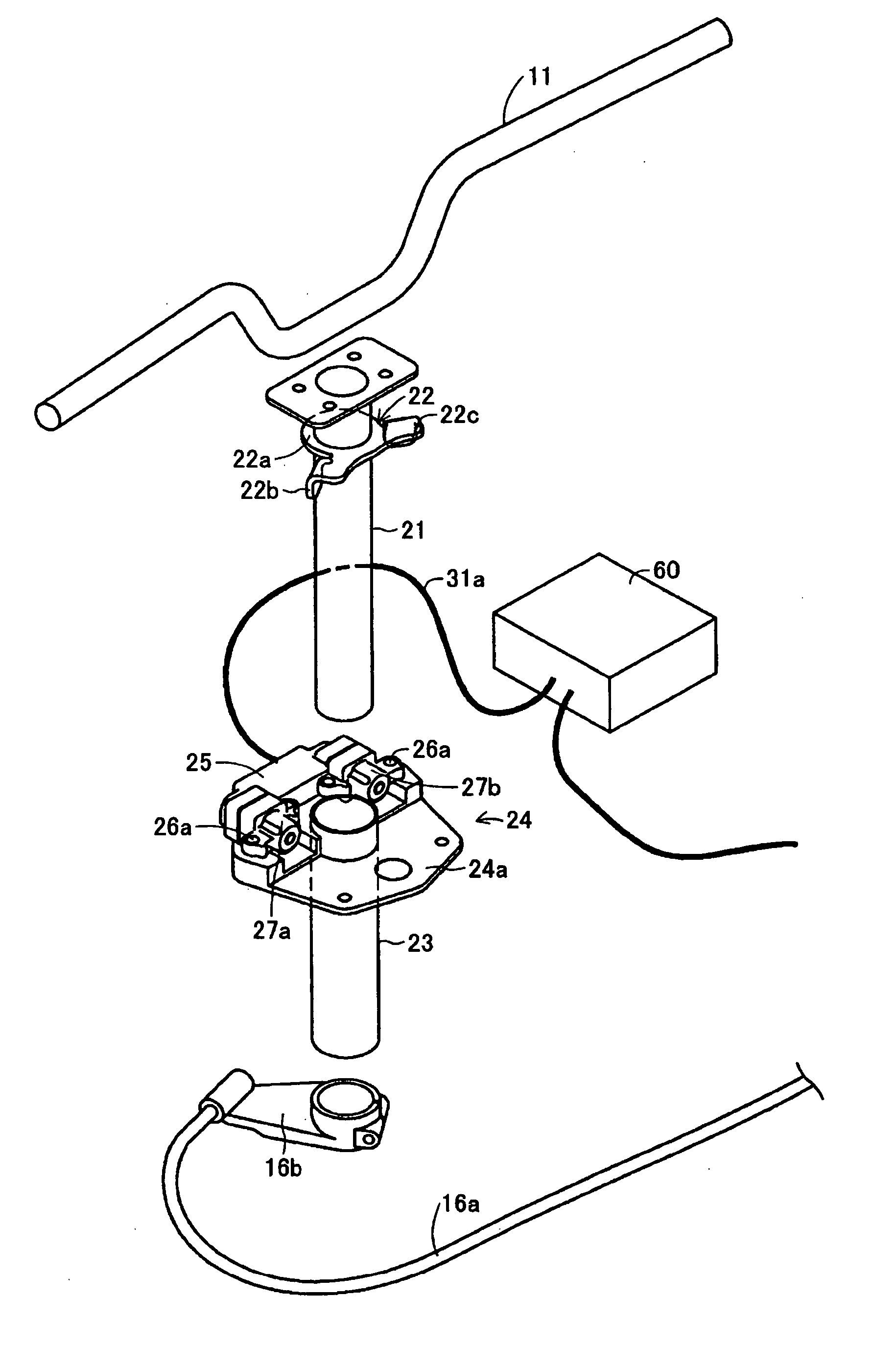
Steering-force detection sections, including a pressure-receiving section and a received-pressure detection section, are spaced from one another in the vicinity of a steering shaft. The steering shaft can include a pressing member for applying pressure to the pressure-receiving section when steering handlebars are rotated in either direction to the maximum steering angle. The pressure-receiving section and the received-pressure detection section are coaxially mounted in a pressure-receiving section casing and a detection section casing, respectively, through a guide tube, so that the pressure-receiving directions of both the pressure-receiving sections are parallel to one another and perpendicular to the direction in which the steering-force detection sections are spaced. The detection section casing includes mounting openings for mounting the received-pressure detecting sections and an electric circuit board, which is integrally connected to the received-pressure detecting sections. The mounting openings are formed in the same direction as each other and perpendicularly to the pressure-receiving direction of the pressure-receiving section.

Description

PRIORITY INFORMATION [0001] This application claims priority to Japanese patent application Serial No. 2004-189353, filed on Jun. 28, 2004, and to Japanese patent application Serial No. 2004-169257, filed on Jun. 7, 2004, the entire contents of each of these priority applications are hereby expressly incorporated by reference. BACKGROUND OF THE INVENTIONS [0002] 1. Field of the Inventions [0003] The present inventions relate to a steering-force detection device for a steering handle of a vehicle. [0004] 2. Description of the Related Art [0005] Many conventional vehicles are steerable by operating a steering handle. Such vehicles include small planing boats, for example. [0006] Some small planing boats are provided with a throttle lever disposed in the vicinity of a grip of the steering handle. The engine is operated to propel the boat according to operation of the throttle lever, and the moving direction of the boat is changed according to operation of the steering handle. In some c...

Claims


Application Information

Patent Timeline
Patent Type & Authority Applications(United States)
IPC IPC(8): B63B35/73
CPCB63B35/731G01L5/221B63H25/52B63H25/02B63B34/10
Inventor KANEKO, YOSHIYUKIHARADA, YOSHINORIMIZUNO, YUTAKAKOYANAGI, TOMOYOSHI
Owner YAMAHA MARINE KK
Learn More