Intake system for combustion engine

a combustion engine and intake system technology, applied in the direction of machines/engines, combustion-air/fuel-air treatment, cycle equipment, etc., can solve the problems of reducing intake efficiency, limited air intake space above the suction duct, and limited size and shape of the fuel intake passage in the conventional intake system, so as to achieve smooth introduction into the suction duct, low leakage of fuel, and high intake efficiency

Active Publication Date: 2006-03-02
KAWASAKI MOTORS LTD
View PDF5 Cites 15 Cited by
  • Summary
  • Abstract
  • Description
  • Claims
  • Application Information

AI Technical Summary

Benefits of technology

[0006] In view of the foregoing, the present invention has an object to increase the intake efficiency in an intake system of a combustion engine including at least one fuel injector disposed in an intake passage.
[0008] According to the present invention, since the height of the rear wall area of the suction duct is chosen to be greater than that of the front wall area, the air tending to flow over the suction duct can be more sucked into the suction duct as deflected by the rear wall area higher than the front wall area, as compared with the suction duct having the rear wall area and the front wall area of the same height. In other words, the effective opening area of the suction duct (the intake area through which the air flows into the suction duct) can increase. Thus, more air can be introduced into the suction duct, resulting in increase of the intake efficiency.
[0011] In another preferred embodiment of the present invention, the rear wall area of the suction duct has an upper end held substantially level with or higher than a fuel injection port of the fuel injector. According to this structural feature, the fuel injected from the fuel injection port is prevented from being carried rearward by the air beyond the suction duct, resulting in little leakage of the fuel from the suction duct.
[0012] In a further preferred embodiment of the present invention, the suction duct has a pair of side wall areas connecting between the front and rear wall areas. Each of the side wall areas has an upper end curved downwardly thereof to form a dent edge. This is particularly advantageous in that with respect to the direction of flow of the air within the intake passage, the air can be also sucked into the suction duct from laterally thereof and, therefore, more air can be introduced into the suction duct with high intake efficiency.
[0013] The suction duct may have an upstream duct portion that is curved to incline forwardly to have an inlet opening directed forwardly upwardly with respect to the direction of flow of the air. According to this structural feature, the air can be smoothly introduced into the suction duct.

Problems solved by technology

However, with compactization of the motorcycle advanced, the fuel intake passages in the conventional intake system are limited as to their size and shape.
In particular, since the second fuel injector is arranged above (upstream of) the suction duct that protrudes into the air cleaner as discussed above, the air intake space above the suction duct is limited, resulting in the intake efficiency being lowered.

Method used


Image

  • Intake system for combustion engine
  • Intake system for combustion engine
  • Intake system for combustion engine

Examples


first embodiment

[0033]FIG. 4 schematically illustrates a view similar to FIG. 3, showing the intake system according to the second preferred embodiment of the present invention. The upper end 22ca of each of the side wall areas 22c of the suction duct 22 extends straight in contrast to the curved configuration employed in the More specifically, when viewed laterally, the upper end 22ca connects the upper end 22aa of the front wall area 22a and the upper end 22ba of the rear wall area 22b while extending straight therebetween.

[0034] Even in this second embodiment, since the rear wall area 22b has a height greater than that of the front wall area 22a as is the case with that in the first embodiment, the effective opening area of the suction duct 22 (the intake surface area) can increase in effect, as compared with the suction duct having the rear wall area 22b and the front wall area 22a of the same height. Accordingly, a substantially large amount of air can be sucked into the suction duct 22, resu...

second embodiment

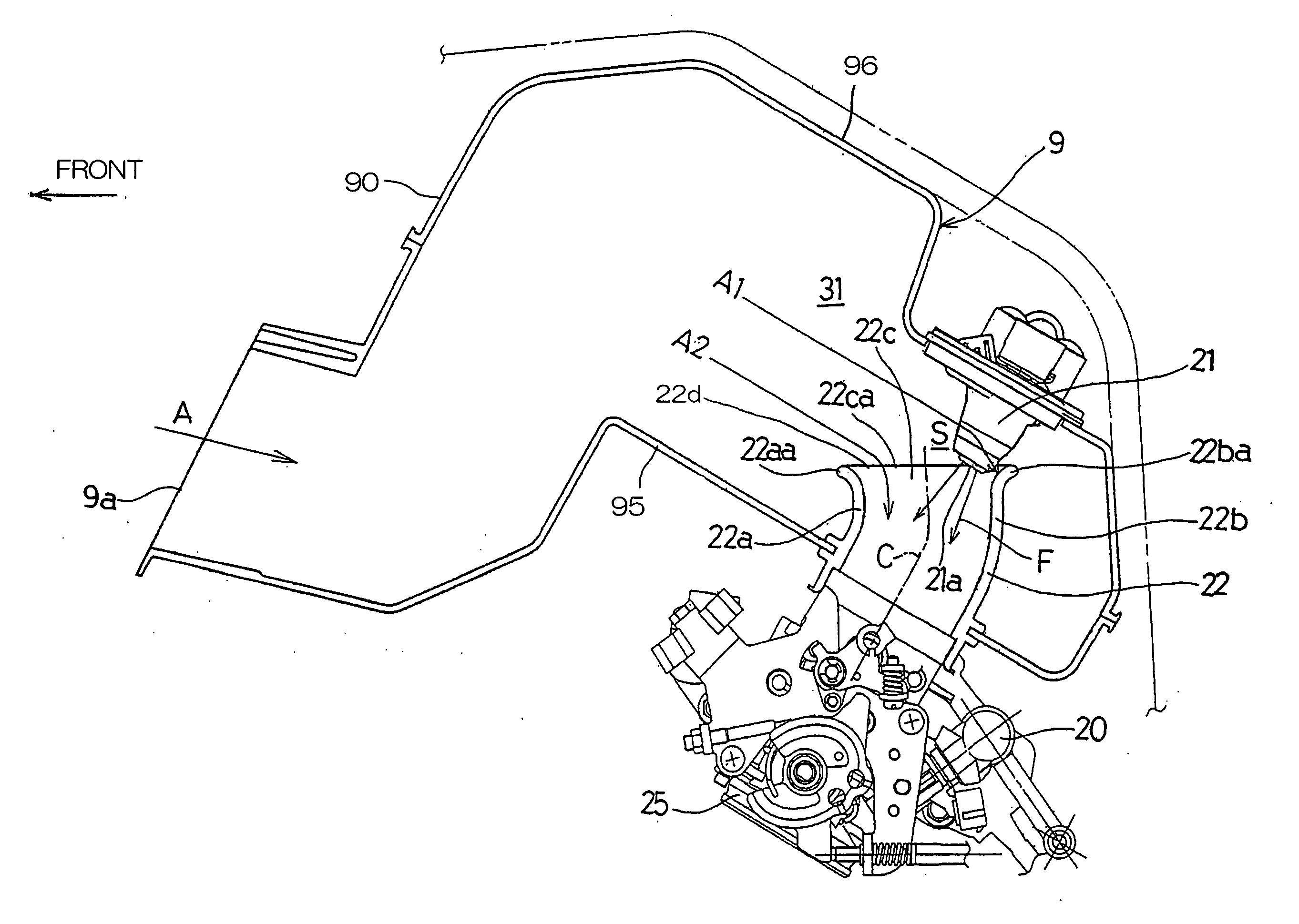
[0036]FIG. 5 illustrates a view similar to FIG. 4, showing the fuel intake system according to a third preferred embodiment of the present invention. This intake system is similar to that of the second embodiment in that the upper end 22ca of the side wall area 22c connects straight the upper end 22aa of the front wall area 22a and the upper end 22ba of the rear wall area 22b. However, the suction duct 22 has its longitudinal axis C in the upstream duct portion smoothly curved or inclined forwardly so that the inlet opening 22d directs forwardly and upwardly to slantwisely encounter to the direction of flow of the air A. Accordingly, the airs A1 and A2 can be smoothly introduced into the suction duct 22.

third embodiment

[0037] Even in this third embodiment, the rear wall area 22b is chosen to have a height greater than that of the front wall area 22a and the upper end 22ba of the rear wall area 22 is held at a level higher than that of the fuel injection port 21a of the fuel injector 21. Accordingly, not only can the amount of the air being introduced into the suction duct 22 be increased with the consequent increase in intake efficiency, but also the fuel F injected from the fuel injection port 21a is prevented from being carried rearward by the airs A1 and A2 beyond the rear wall area 22b, resulting in little leakage of the fuel F from the suction duct 22.

[0038] It is to be noted that in FIG. 5, the cleaner element 32 shown in FIG. 2 is not shown for the sake of brevity.

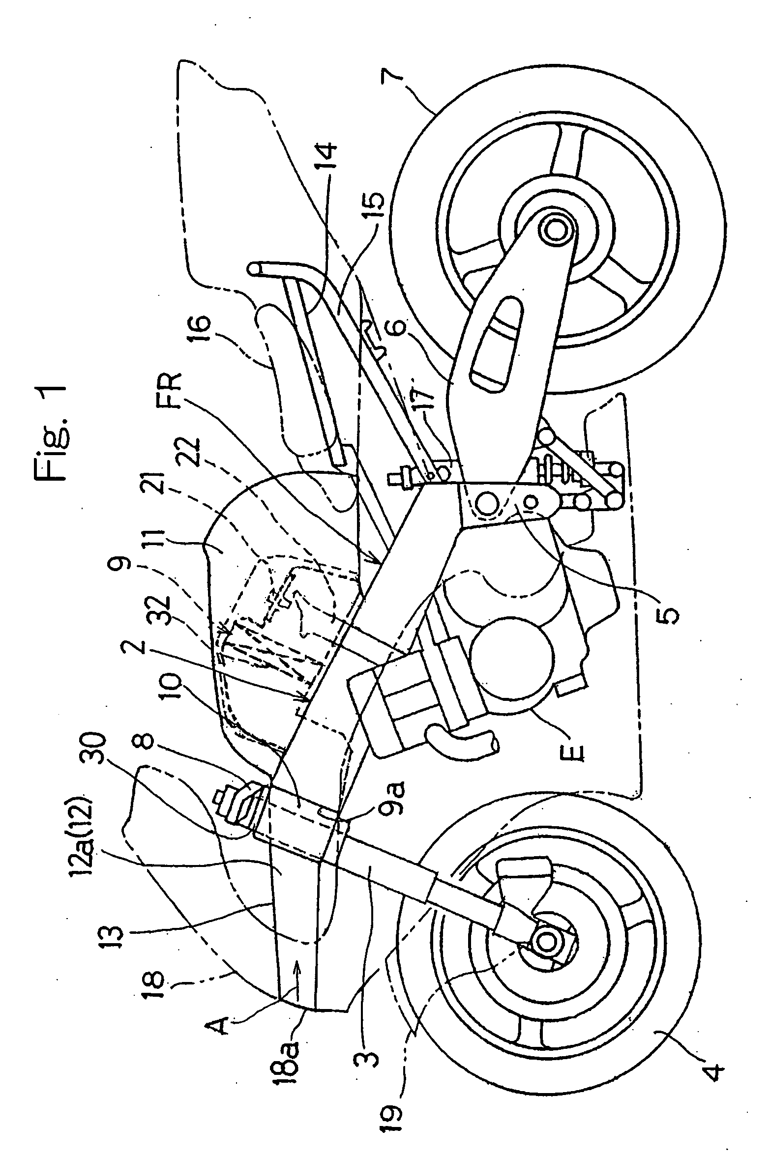
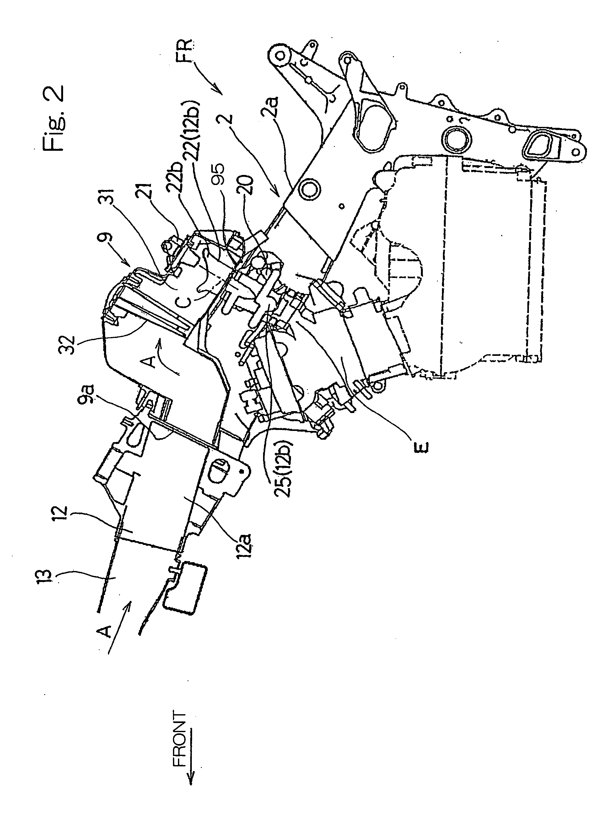
[0039] When the intake system according to any one of the foregoing embodiments is employed in the multi-cylinder combustion engine, the suction ducts 22 communicated with respective engine cylinders may be arranged to have diffe...


PUM


Abstract

An intake system for a combustion engine includes an intake passage (12), a suction duct (22) protruding into the intake passage (12) to communicate therewith and having front and rear wall areas (22a and 22b), and a fuel injector (21) positioned upstream of the intake duct (22) for injecting fuel (F) into the suction duct (22). The rear wall area (22b) has a height greater than that of the front wall area (22a).

Description

BACKGROUND OF THE INVENTION [0001] 1. Field of the Invention [0002] The present invention relates to an intake system for a combustion engine, particularly that used in a motorcycle. [0003] 2. Description of the Prior Art [0004] As a high power combustion engine for racing motorcycles, the combustion engine has hitherto been well known, in which first and second fuel injectors are employed in each of intake passages leading to respective engine cylinders and are operated simultaneously during a high power operation. The first and second fuel injectors are positioned downstream of a throttle valve in a throttle body and upstream of an suction duct protruding into an air cleaner forming a part of the intake passage, respectively. In this combustion engine, the distance between an injection port of the second fuel injector and a combustion chamber of the engine is set long by positioning the second fuel injector within the air cleaner distant from the combustion chamber. This structura...

Claims


Application Information

Patent Timeline
Patent Type & Authority Applications(United States)
IPC IPC(8): F02M35/10F02M51/00B62J99/00
CPCF02B17/00F02B31/087F02D9/1065F02M9/08F02M35/02F02M35/10039Y02T10/14F02M35/10216F02M35/108F02M35/162F02M69/043Y02T10/12Y02T10/146F02M35/10177
Inventor FUKAMI, TAKASHIMORI, TETSUYA
Owner KAWASAKI MOTORS LTD
Why Eureka
Try Eureka