Seat belt restraint and energy absorber

a seat belt and energy absorber technology, applied in the field of seat belt restraint and energy absorber, can solve the problems of excessive load acting on the body of the vehicle occupant, and achieve the effect of keeping the length of the belt constan

Inactive Publication Date: 2006-03-02
FORD GLOBAL TECH LLC
View PDF33 Cites 14 Cited by
  • Summary
  • Abstract
  • Description
  • Claims
  • Application Information

AI Technical Summary

Benefits of technology

[0015] Moving the effective side positions forwardly with respect to the seat during deceleration in a crash situation allows for some forward excursion of the occupant, and also enables adjustment of the angle which the belt forms with respect to the seat. Accordingly, the horizontal load on the occupant may be limited without excessive slanting of the belt. Also, the forward movement of the effective side positions allows for maintaining a favourable angle of the belt even as the occupant's pelvis slides forward on the seat in a case of a crash from the forward direction. The forward movement of both occupant and the effective side positions can therefore reduce deceleration forces on the lower torso and reduce peak belt loads.
[0018] Preferably, the belt guides may be movable in a forward direction for accomplishing the movement of the effective side positions in a direction having a forward component. This allows for several simple constructions, having the further advantage that the length of the belt may be kept constant during the movement from the crash restraint configuration to the ride down configuration. However, it is possible to accomplish the movement of the effective side positions in a forward direction also by moving the belt guides in other directions, such as a downward direction. In this case, it might be necessary to simultaneously lengthen the belt so as to accomplish a forward (not rearward) movement of the effective side positions.

Problems solved by technology

However, excessive slanting might cause the belt to ride up toward the abdomen during a crash, which might result in excessive loads acting on the body of the vehicle occupant.

Method used


Image

  • Seat belt restraint and energy absorber
  • Seat belt restraint and energy absorber
  • Seat belt restraint and energy absorber

Examples


first embodiment

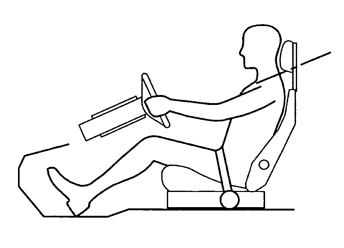
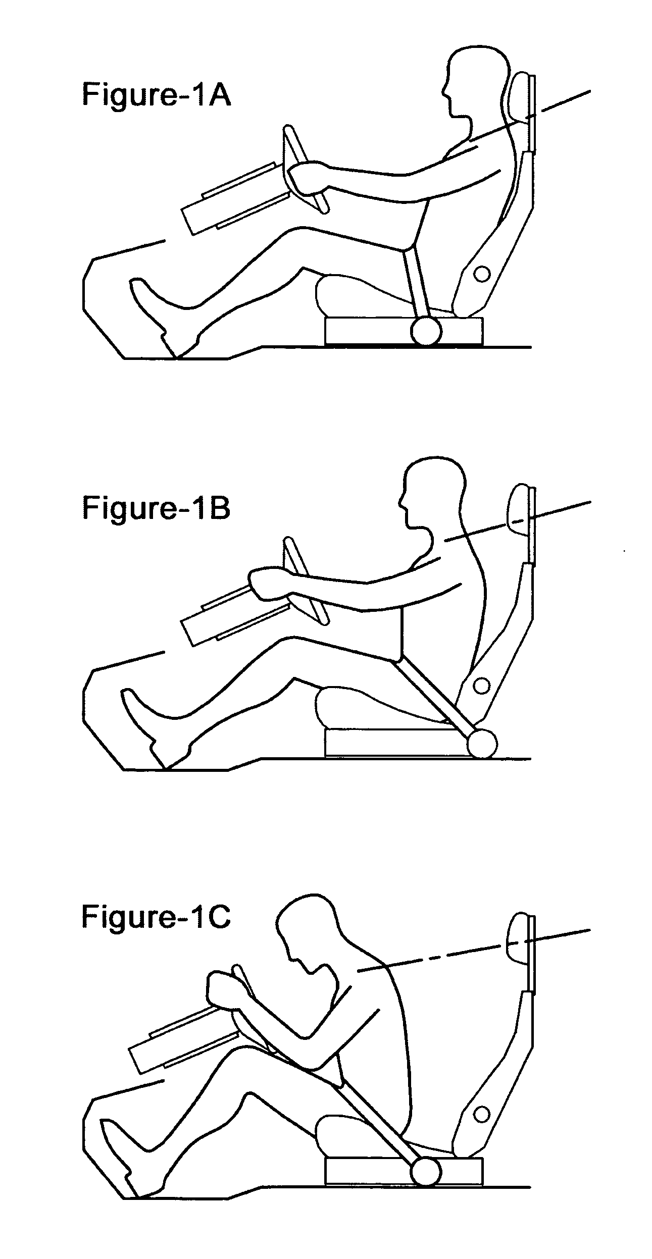
[0040]FIGS. 1a to 1c illustrate the invention when used in a system having an initial comfort situation as depicted in FIG. 1a. The vehicle occupant restraint system is schematically shown when used by an occupant 1 being seated in a seat 2, in this case a driver's seat. The vehicle occupant restraint system comprises a belt 3, which extends from an effective belt guide 4 on each side of the seat 2. The belt emerges from the sides of the seat 2 at the effective side positions P. In FIGS. 1a-1c the belt 3 is a lap belt, which may advantageously be a part of a three-point belt having an additional shoulder portion 3′, being schematically depicted only.

[0041] In FIG. 1a, the belt is assuming a comfort configuration for normal driving situations. In the comfort configuration, the belt 3 is fastened about the occupant 1 and extends down to the effective side positions P at the side of the occupant's thigh, in a relatively vertical direction. This configuration is chosen because a positio...

fourth embodiment

[0071]FIG. 5c illustrates the subsequently following step where the belt is brought to a crash restraint configuration, e.g. the belt guide 4 is moved rearward. This configuration, as well as the set up for the ride down configuration including the load limiter device is similar to that described in relation to FIGS. 2a to 2c, and reference is made thereto for the function of this (See also FIG. 1b, 1c)

[0072]FIGS. 6a to 6c illustrate a fifth embodiment of an arrangement suitable for implementing the first embodiment of the invention, which is similar to the system of FIGS. 5a to 5c in that a pre-tension step is performed before the crash restraint configuration is attained. FIGS. 6a and 6b are intended to illustrated the pre-tensioning step only, which is why features relating to the altering between the crash restraint configuration and the ride down configuration are omitted from these figures and appear only in FIG. 6c.

[0073] The embodiment of FIGS. 6a to 6c differs from that o...

second embodiment

[0074]FIGS. 7a to 7c illustrate an arrangement suitable for the invention, wherein the belt guide 4 is rotationally displaced for accomplishing the displacement of the effective side positions P. The belt guide 4 is in this case associated to a first end of a rotational arm 19 whose other end is rotationally fixed at a centre 20. The belt guide is connected to the wire 7 continuing with the belt 3.

[0075]FIG. 7a shows the system in an initial comfort configuration. FIG. 7b shows the system in a crash restraint configuration in which the belt guide 4 has been moved rearwardly with respect to the comfort configuration by counter clockwise rotation of the arm 19. FIG. 7c shows the system in a ride down configuration, where the belt guide 4 has been moved forwardly with respect to the crash restraint configuration by further counter clockwise rotation of the arm 19. The function of this embodiment will essentially be the same of the first embodiment depicted in FIGS. 1a to 1c, although t...


PUM


Abstract

The invention relates to a vehicle occupant restraint system comprising a belt extending from two effective belt guides (4) located on each side of a seat (2) and which when fastened around an occupant (1) has a belt configuration defined by at least two effective side positions (P) where the belt emerges on each side of the seat, wherein said effective belt guides (4) are arranged to be movable upon acceleration of the occupant (1) in relation to the seat (2) in a crash situation so as to accomplish a forward displacement of the effective side positions (P) in relation to the seat (2) for altering the belt configuration from a crash restraint configuration to a ride down configuration.

Description

FIELD OF INVENTION [0001] The present invention relates to a vehicle occupant restraint system comprising a belt extending from two effective belt guides located on each side of a seat and which when fastened around an occupant has a belt configuration defined by at least two effective side positions where the belt emerges on each side of the seat. BACKGROUND OF INVENTION [0002] Vehicle occupant restraint systems include belts for restraining a vehicle occupant to a seat of the vehicle in case of a crash. When fastened around a vehicle occupant, the belt will attain a belt configuration which is defined by at least two effective side positions where the belt emerges from each side of the seat. [0003] The configuration of the belt in a crash situation is herein referred to as a crash restraint configuration. In many restraint systems, the crash restraint configuration is the normal configuration which the belt attains as soon as it is fastened around the occupant. [0004] Since any re...

Claims


Application Information

Patent Timeline
Patent Type & Authority Applications(United States)
IPC IPC(8): B60R21/00B60R22/195B60R22/28B60R22/46
CPCB60R22/1951B60R22/1952B60R2022/4609B60R22/28B60R22/1955
Inventor MENDIS, KOLITA
Owner FORD GLOBAL TECH LLC
Why Eureka
Try Eureka