

Scalloped rack or shelf for floral merchandiser
- Summary
- Abstract
- Description
- Claims
- Application Information
AI Technical Summary
Benefits of technology
Problems solved by technology
Method used
Image

Examples
Embodiment Construction
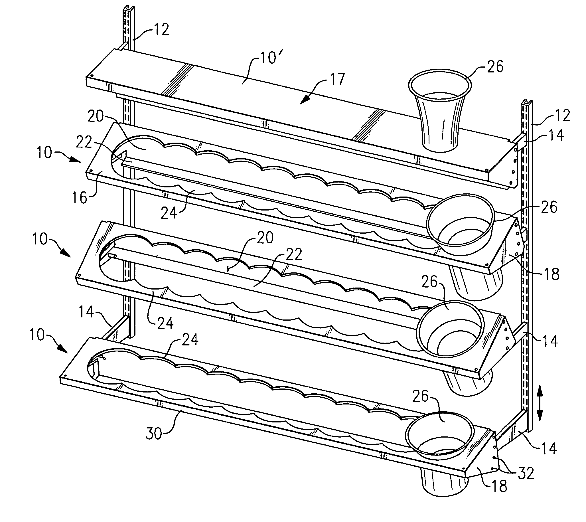
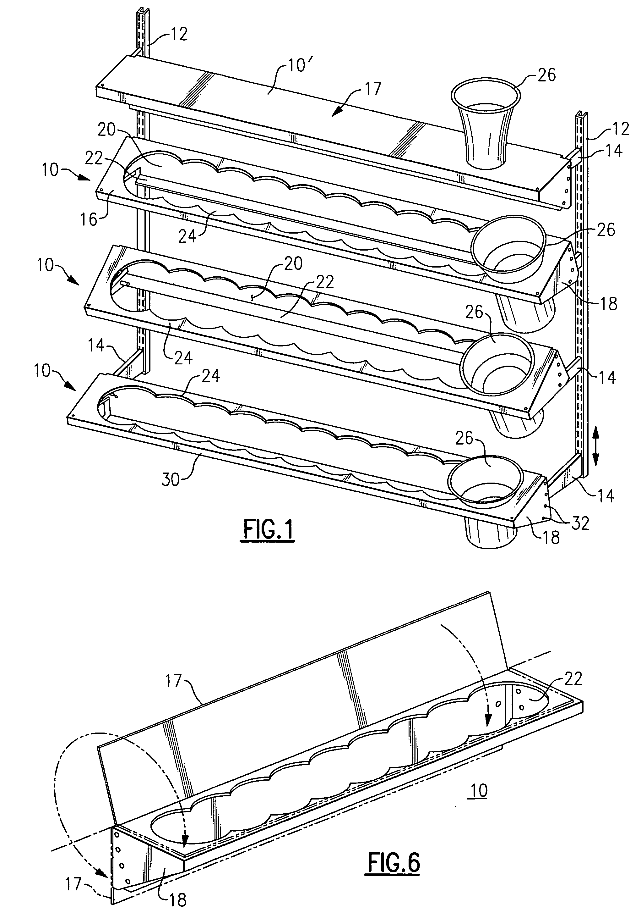
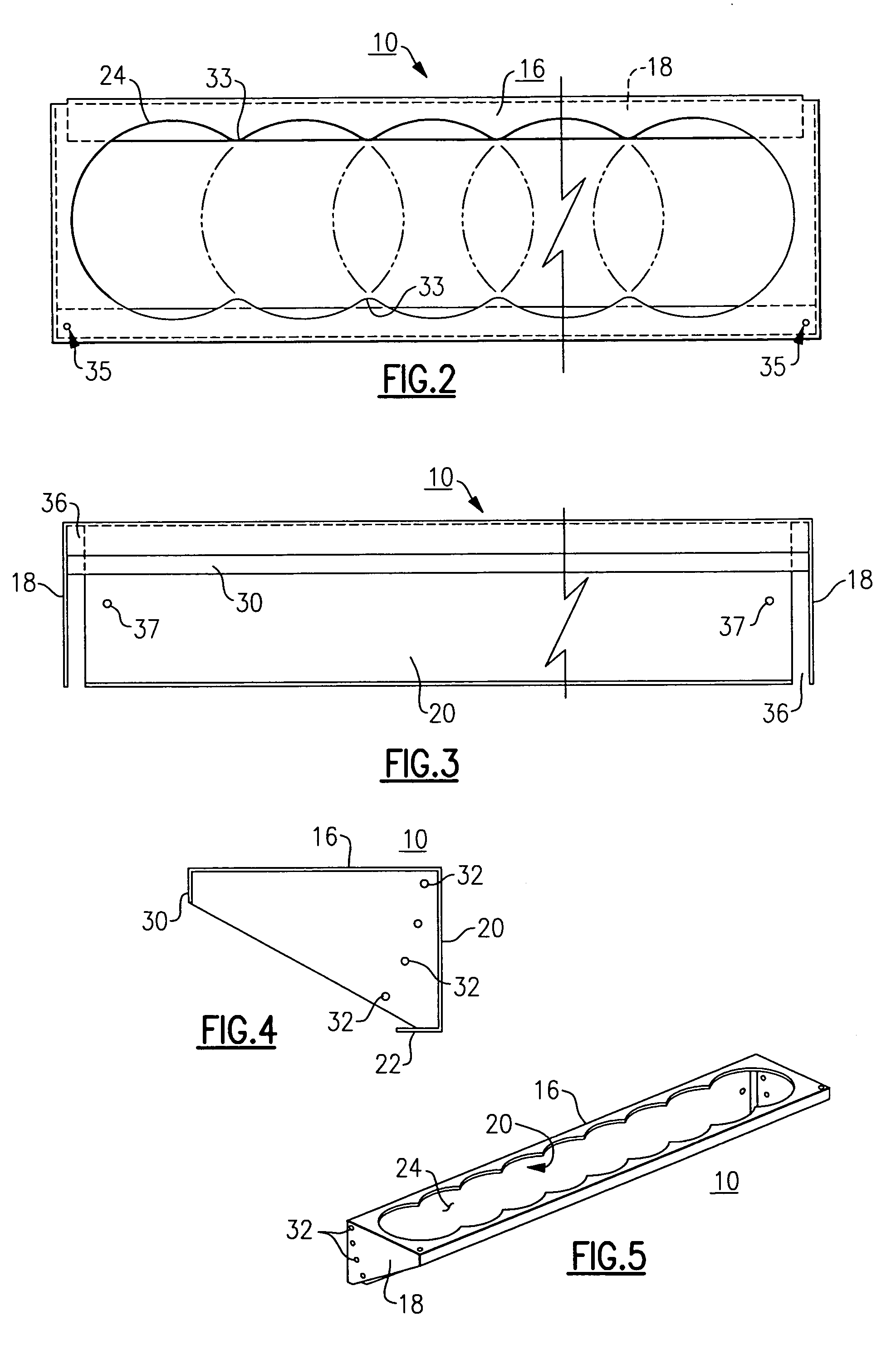
[0024] With reference to the drawing Figures, FIG. 1 shows a number of scalloped display shelves 10 arranged on a pair of vertical standards 12, which can be on the back wall of a floral display cabinet (not shown) of the type illustrated and disclosed in my Design Pat. No. D496,053. Each shelf 10 has a right-side and left-side strut 14 that fits into the respective vertical standard 12, and can be adjusted both in the pitch angle of the shelf 10 and in the distance of the shelf from the standards 12 and back wall. Each shelf 10 in this embodiment has a top panel 16 that is generally horizontal, left and right side walls 18 each of generally trapezoidal shape, a back wall 20 that is generally vertical, and a flange or lip 22 along the lower edge of the back wall 20.
[0025] The top panel 16 of each of the shelves has an elongated scalloped or wavy cutout 24 formed of a series of overlapping circular voids, and defining a series of lateral positions for round containers of vases 26, a...
PUM
 Abstract
Description
Claims
Application Information