This helps you quickly interpret patents by identifying the three key elements:
Problems solved by technology
Method used
Benefits of technology
Benefits of technology
[0007] An advantage of the present invention is to provide an IC card with higher security.
[0008] According to an aspect of the invention, an IC card includes a capacitance-type fingerprint sensor and a display device displaying an encrypted image that is readable by an external device.
[0009] An authentication of a user of the IC card can be carried out with the provided capacitance-type fingerprint sensor. Therefore, the user can be limited to a specific user and a misuse of the IC card is prevented.
[0010] The IC card according to the aspect of the invention not only used to conduct the above-mentioned authentication but also has the display device displaying the encrypted image which can be read by the external device. Therefore, the IC card with higher security can be realized since the information-communication through the encrypted image is possible in addition to the fingerprint authentication.
[0011] Meanwhile, as means of the information-communication, antennas may be provided in the IC card and the external device can be used to electromagnetically communicate. However, such electromagnetic means may or may not be used according to the aspects of the invention. The
Problems solved by technology
However, techniques described in the above-mentioned examples, which are used in order to provide security for users, are insufficient to ensure strong security for systems.
On the cont
Method used
Image
Click on the blue label to locate the original text in one second.
Reading with bidirectional positioning of images and text.
Examples
Example
First Embodiment of IC Card
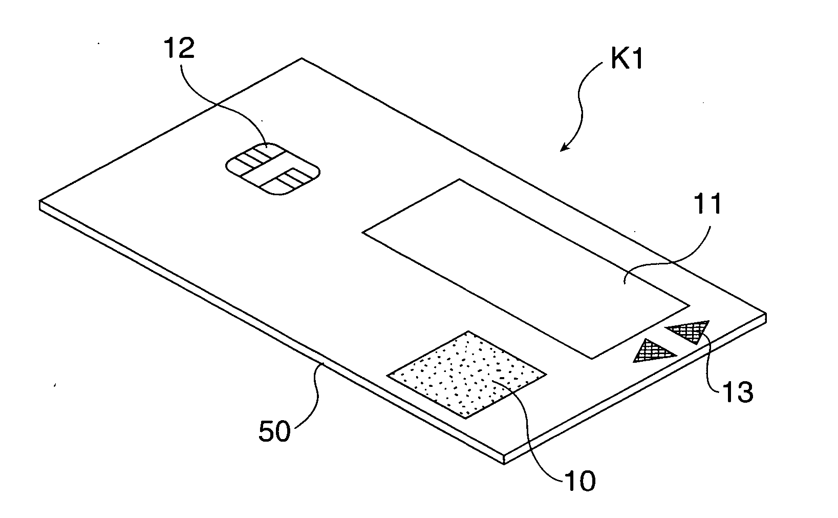
[0043]FIG. 1 is a perspective view of an IC card K1 according to a first embodiment and FIG. 2 is a plan view of the IC card K1.
[0044] IC card K1 includes a substrate 50, a fingerprint sensor 10, an electrophoretic display 11 (hereinafter, “EPD”) (a display device), a connecting IC terminal 12 (a terminal for external connection) and a switch 13 (means of selection). The substrate 50 consists of two substrates made of plastic and the like. An integrated circuit (a control unit) such as an IC chip that may be interposed between the two plastic substrates is provided in the substrate 50.
[0045] Next, substantial parts of the IC card K1 are described in detail with reference to FIG. 3-5.
(Fingerprint Sensor)
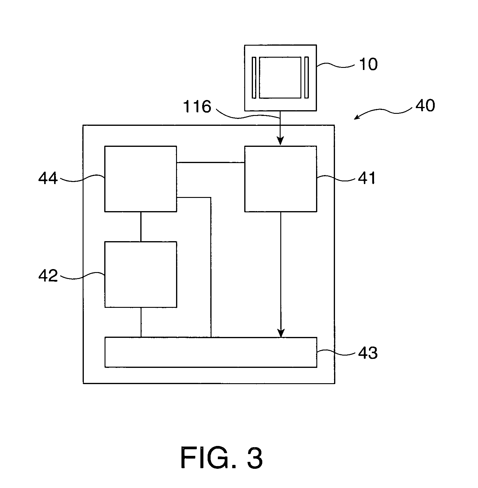
[0046]FIG. 3 is a block diagram for explaining a processing unit 40 which processes information inputted from the fingerprint sensor 10. FIG. 4 schematically shows a structure of the fingerprint sensor 10.
[0047] As shown in FIG. 3, the processing unit...
Example
Second Embodiment of IC Card
[0102] Next, a second embodiment of the invention will be described.
[0103]FIG. 8 is a perspective view of an IC card K3 of the second embodiment. In this embodiment, the IC card K3 has a membrane switch 15 (means of selection).
[0104] In the second embodiment, the same structures as those of the above-described first embodiment are given the identical numerals and those explanations will be omitted.
[0105] The membrane switch 15 is for selecting and determining an application which is available in the IC card K3. A plurality of applications is displayed on the EPD 11. The applications displayed on the EPD 11 is selected and determined by using the membrane switch 15.
[0106] The membrane switch 15 is not only used for selecting and determining the application but also for switching the power of the IC card K3 to the ON state (power on) from the OFF state (power off).
[0107] Such membrane switch 15 is coupled to the IC chip embedded in the IC card K3. The...
PUM
Abstract
An IC card including a capacitance type fingerprint sensor and a display device displaying an encrypted image that is readable by an external device is described.
Description
BACKGROUND OF THE INVENTION [0001] 1. Technical Field [0002] Aspects of the present invention relate to an integrated circuit (IC) card having a fingerprint sensor. [0003] 2. Related Art [0004] An IC card (Smart Card) is a card in which an integrated circuit (IC) is embedded. Compared with a magnetic strip card, the IC card has many advantages such as high information capacity, increased security (prevention of forgery and alteration), compatibleness with multiple applications, and load reduction of a host (off-line processing is possible). For these reasons, the IC card is starting to see introductions in the electric money and electric commerce fields, medical and health fields, transportation fields including railroads and route buses, security fields (such as a control of access to buildings) and other fields, in addition to card applications such as credit cards and ATM cards. In keeping with this trend, an IC card having a fingerprint sensor and a function of identification is...
Claims
Application Information
Patent Timeline
Application Date:The date an application was filed.
Publication Date:The date a patent or application was officially published.
First Publication Date:The earliest publication date of a patent with the same application number.
Issue Date:Publication date of the patent grant document.
PCT Entry Date:The Entry date of PCT National Phase.
Estimated Expiry Date:The statutory expiry date of a patent right according to the Patent Law, and it is the longest term of protection that the patent right can achieve without the termination of the patent right due to other reasons(Term extension factor has been taken into account ).
Invalid Date:Actual expiry date is based on effective date or publication date of legal transaction data of invalid patent.

