Arrangement for detecting the position of a damper blade using a wireless communication sensor

a wireless communication and sensor technology, applied in the field of damper blade detection, can solve the problems of inability to reliably produce the level of accuracy that is necessary, inefficiency of further opening the damper that is fully open, and damage to the vav unit, so as to remove inaccuracy

Active Publication Date: 2006-03-09
SIEMENS IND INC
View PDF13 Cites 35 Cited by
  • Summary
  • Abstract
  • Description
  • Claims
  • Application Information

AI Technical Summary

Benefits of technology

[0011] The present invention addresses the above-described needs, as well as others, by providing a sensor module coupled directly to the damper blade. Preferably, the sensor module includes wireless communication capabilities. Use of a sensor module that is directly coupled to the damper blade removes inaccuracies due to the indirect measurement techniques of the prior art. The sensor module is preferably calibrated prior to use, but in some cases may be used with little or no calibration.

Problems solved by technology

Inaccurate position information can even result in damage to a VAV unit.
The attempt to further open the damper that is fully open is both inefficient and potentially harmful to the equipment.
The types of damper position measurements that are currently used cannot always reliably produce the level of accuracy that is necessary for high quality performance of control systems.
However, calibration techniques only provide limited improvement.
Moreover, some degradation of accuracy can occur over time due to the nature of mechanical linkages, thereby reducing the effectiveness of the initial calibration.
However, limit switches can provide little information regarding the position of the blades.

Method used


Image

  • Arrangement for detecting the position of a damper blade using a wireless communication sensor
  • Arrangement for detecting the position of a damper blade using a wireless communication sensor
  • Arrangement for detecting the position of a damper blade using a wireless communication sensor

Examples


Embodiment Construction

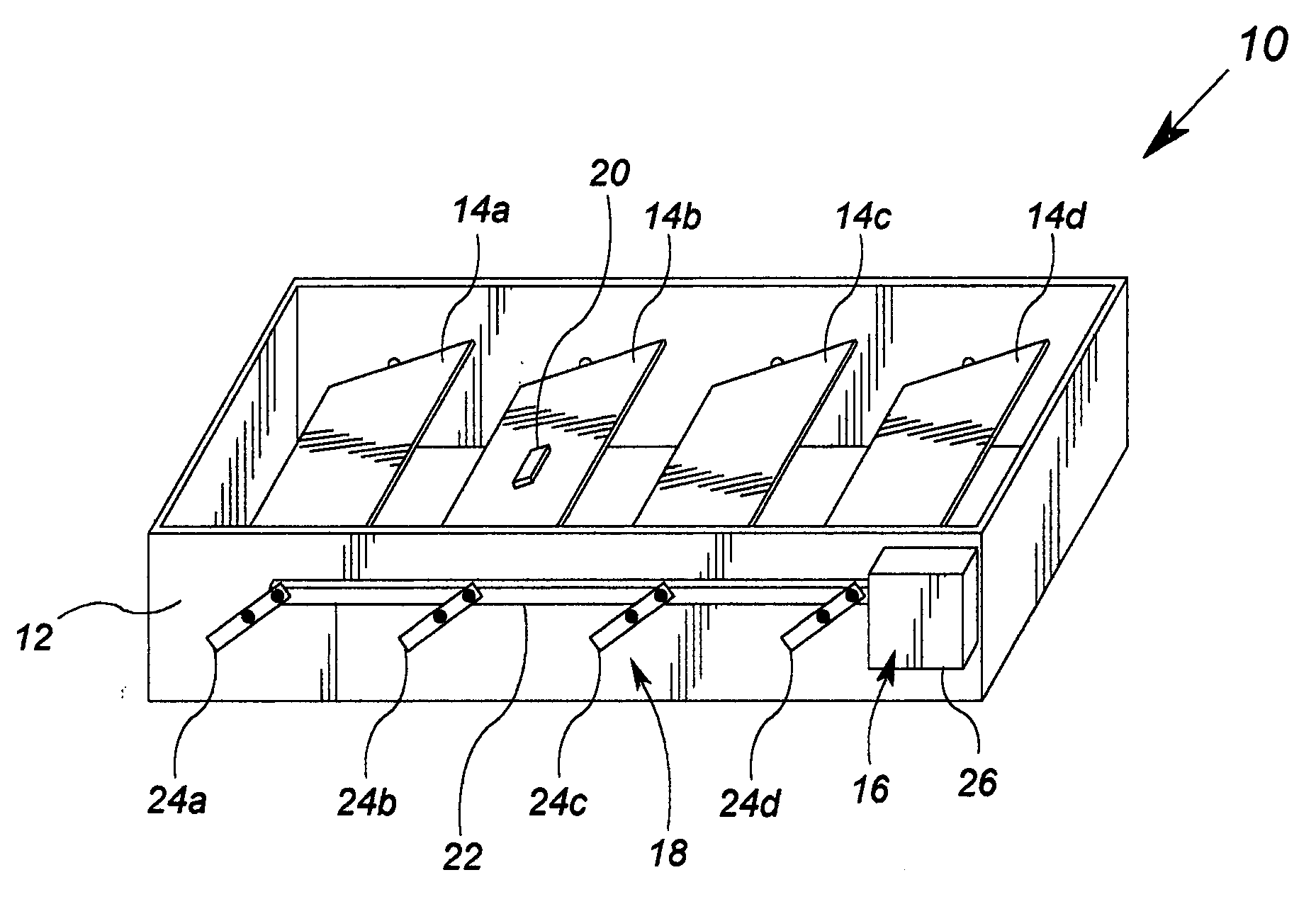
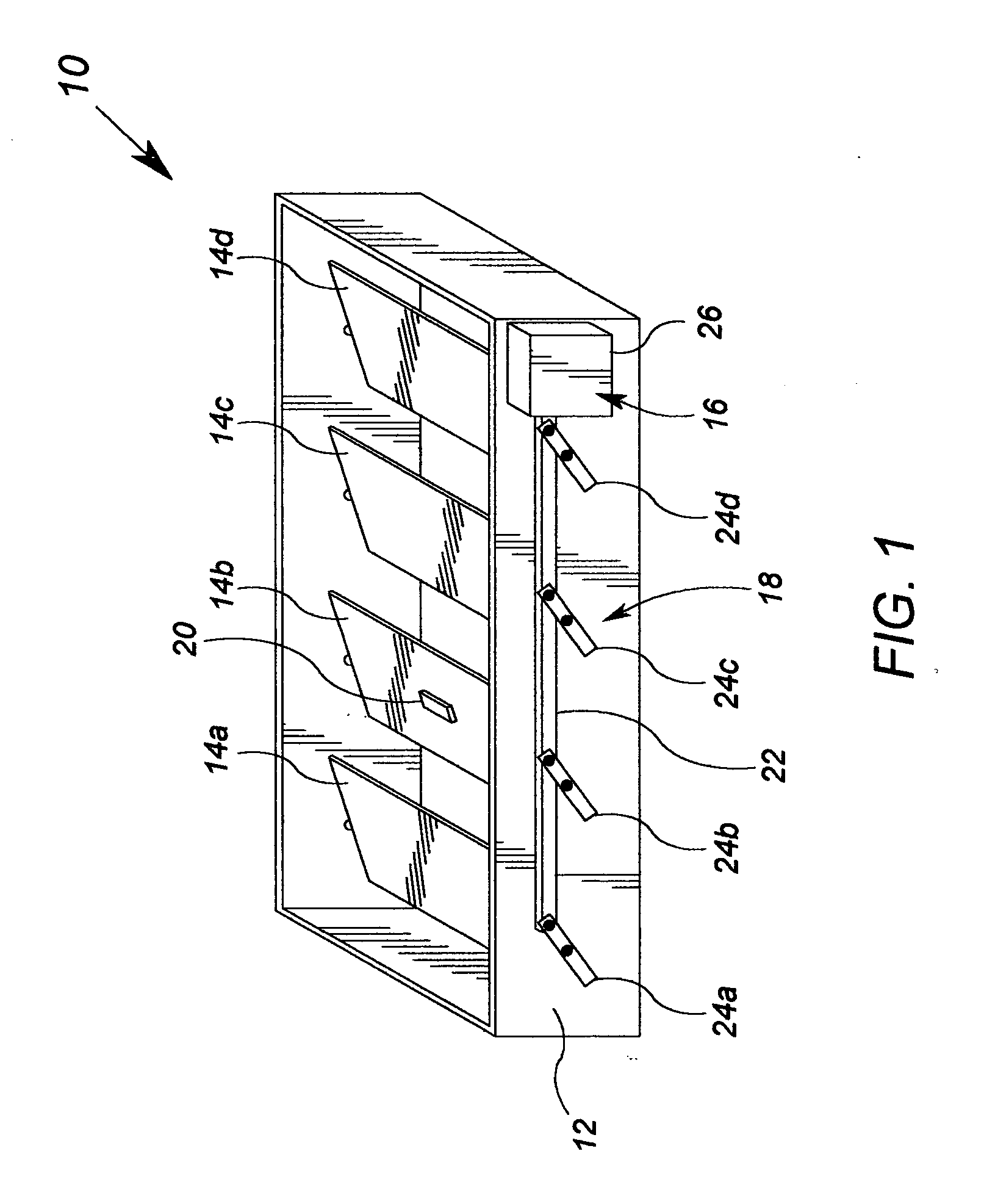
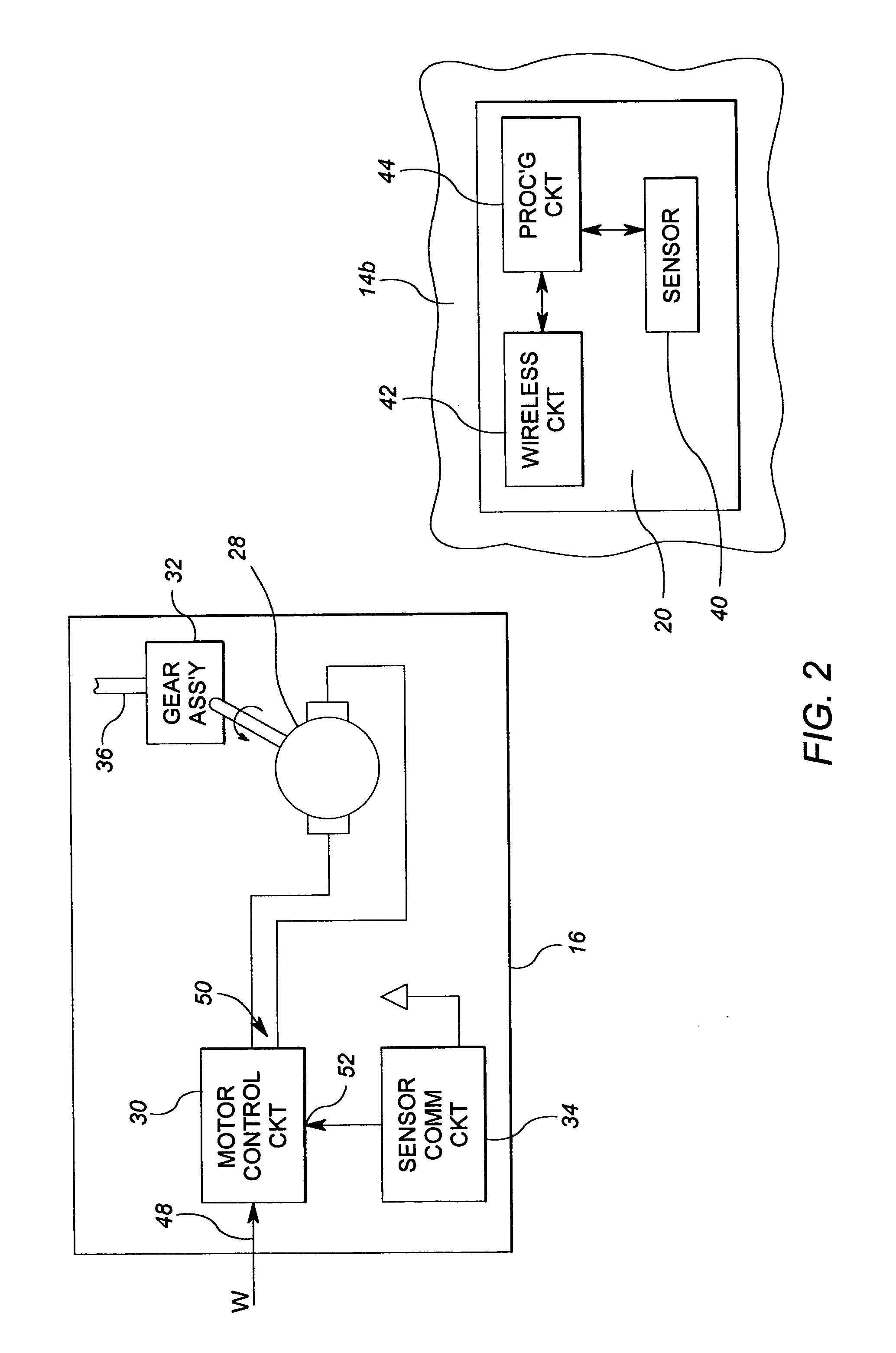
[0020]FIG. 1 shows a perspective view of an exemplary damper assembly 10 according to the present invention. The electrical components of the damper assembly 10 are illustrated in FIG. 2. Reference is made simultaneously to FIGS. 1 and 2 in the ensuing description. The damper assembly 10 may be employed as a VAV unit.

[0021] The damper assembly includes a damper frame 12, a plurality of damper blades 14a, 14b, 14c, and 14d, an actuator module 16, a linkage assembly 18, and a sensor module 20. The damper frame 12 is a housing for a ventilation damper, which may suitably take the form of any housing for an HVAC ventilation damper or variable air volume (“VAV”) unit. The plurality of damper blades 14a, 14b, 14c and 14d are movably attached to the damper frame 12 to at least partially regulate air flow proximate the damper frame 12. To this end, each of the damper blades 14a, 14b, 14c and 14d may rotate about its own longitudinal axis between a closed or nearly closed position and vario...


PUM


Abstract

A damper assembly includes a damper frame, at least one damper blade, an actuator and a sensor module. The damper blade(s) is / are movably attached to the damper frame to at least partially regulate air flow proximate the damper frame. The actuator is configured to control a position of the at least one damper blade. The sensor module is coupled to a first damper blade and includes a sensor device operable to determine position information regarding the position of the damper blade. The sensor module further includes a wireless communication circuit that is operable to communicate the position information to a second wireless communication circuit disposed off of or away from the damper blade.

Description

[0001] This application claims the benefit of U.S. Provisional Patent Application Ser. No. 60 / 608,268, filed Sep. 9, 2004, and which is incorporated herein by reference.FIELD OF THE INVENTION [0002] The present invention relates to damper blades used for controlling air flow, and more particularly, the devices that detect the position of a damper blade. BACKGROUND OF THE INVENTION [0003] Ventilation dampers are devices that are used, by way of example, to control the flow of air into ventilation ducts, rooms, or other spaces of a building or facility. For example, a ventilation damper may help control the flow of cool air in to a room. In another example, a ventilation damper may control the amount of exhaust air from a building that is recirculated into the fresh air. Ventilation dampers are movable such that they may be further opened or closed in order to increase or decrease, respectively, the flow of air through the damper assembly device. In building control systems, damper as...

Claims


Application Information

Patent Timeline
Patent Type & Authority Applications(United States)
IPC IPC(8): F24F7/00G05D23/00F25B49/00F25D17/04
CPCF24F13/1426F24F2011/0068F24F13/15F24F11/56
Inventor COOK, MATTHEW D.
Owner SIEMENS IND INC
Why Eureka
Try Eureka