In addition, wind can cause a back draft, a reverse flow through a
system.
In the case of a
chimney, this can cause
flue gases to be vented within a building.
These factors create the potential for insufficient draft and
overdraft which may cause undesirable, and even unsafe conditions within the enclosed air system.
In addition, failure to control the quality of air within an enclosed environment, or the flues connected to the appliances for exhausting air, may drastically impede the efficiency and general operation of the appliances since an appliance or group of appliances require specific air flow rates for optimal performance.
This constant flow of air thorough an air system is inefficient and costly.
Three to five thousand cubic feet per minute of air may be expelled by these systems causing loss of heat in the winter and loss of cooled air in the summer.
In the case of intake flows, the mechanically drawn air brought into an air system could provide an undesirable pressure within the system.
In addition, this inflexible flow of air in or out of the air system can again impede the efficiency and general operation of many appliances.
While an improvement over more traditional mechanical draft systems, this method of adjustment is costly and inefficient, and fails to make the precise system-wide adjustments needed to maintain a truly “continuous”
pressure system.
On-off switches and non-variable fan motors may continuously jump through pressure levels in an attempt to maintain pressure, but they are incapable of keeping pressure at precise levels, especially when an air system is dynamically effected by the demands of multiple appliances and changing environmental factors such as wind.
Even those systems that have attempted to implement a single sensor to measure and maintain a characteristic such as pressure do so using these “on-off” techniques, and inevitably jump the fan speed to predetermined and limited levels.
In addition, conventional systems fail to maximize the efficiency and effectiveness, and reduce the cost, associated with controlling their systems since they implement an independent controller for each system, and fail to arm the controllers they do use with effective appliance
interfacing and adaptive technology.
Those conventional systems attempting to monitor and maintain an environmental characteristic, unfortunately, do assign one controller to each air
control system.
Consequently, repetitive circuitry and control structures are required for each system, even when numerous air systems (i.e., venting,
combustion, and heating) are contained within one building.
This presents a significant cost problem, as well as a training and
standardization problem.
The cost problem is significant at the production level, and at the
purchasing level.
In addition, the training and
standardization problem likely increases over time.
Training, usage, and maintenance costs will also increase with the employment of an individual controller at each air
control system.
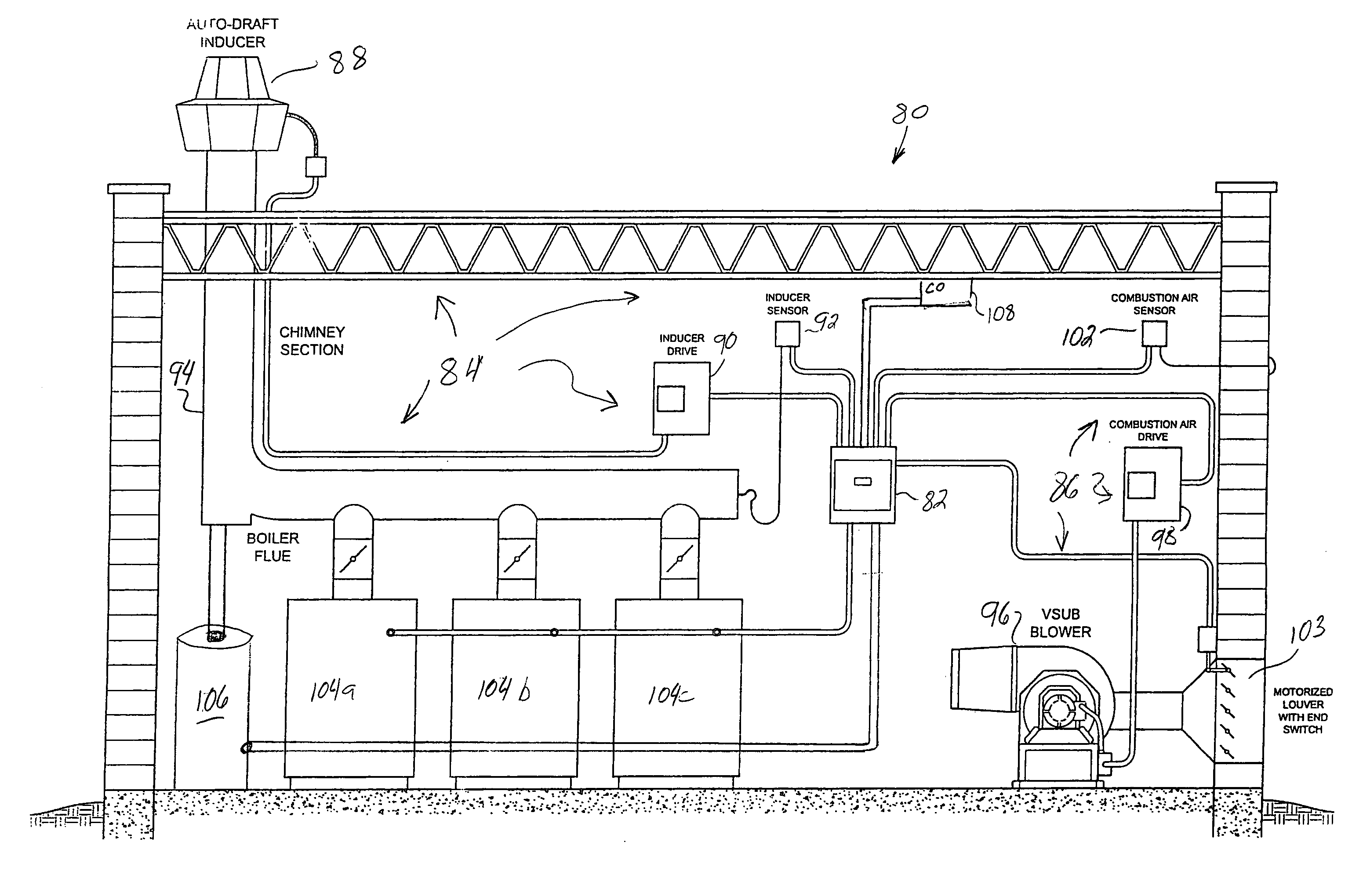
Another problem associated with present-day boiler rooms is the need for multiple dedicated controllers for general boiler room functions, such as mechanical draft control,
combustion air control, appliance control for different types of appliances in the boiler room, staging or sequencing control of appliances, as well as the control of various auxiliary equipment, such as temperature controls for the building, various sensors and detectors for safety purposes, alarms, and the like.
Such systems require substantial
engineering resources to implement, and are generally not easily expandable or adjustable.
This approach does not eliminate the need for multiple separate controllers, each dedicated to its particular function.
Furthermore, such an approach would not likely overcome the problem of the need for a custom-engineered control system since each individual controller can vary substantially from one manufacturer to another.
Another problem prevalent in present-day boiler systems is related to the limited capability of boilers to maintain any given temperature while operating in steady-state.
This creates an unbalance in work load as among a group of boilers in a building since certain boilers will likely be on more than others, and certain boilers are more likely than others to be cycled on and off.
These asymmetries in usage patterns results in reduced overall time between boiler maintenance.
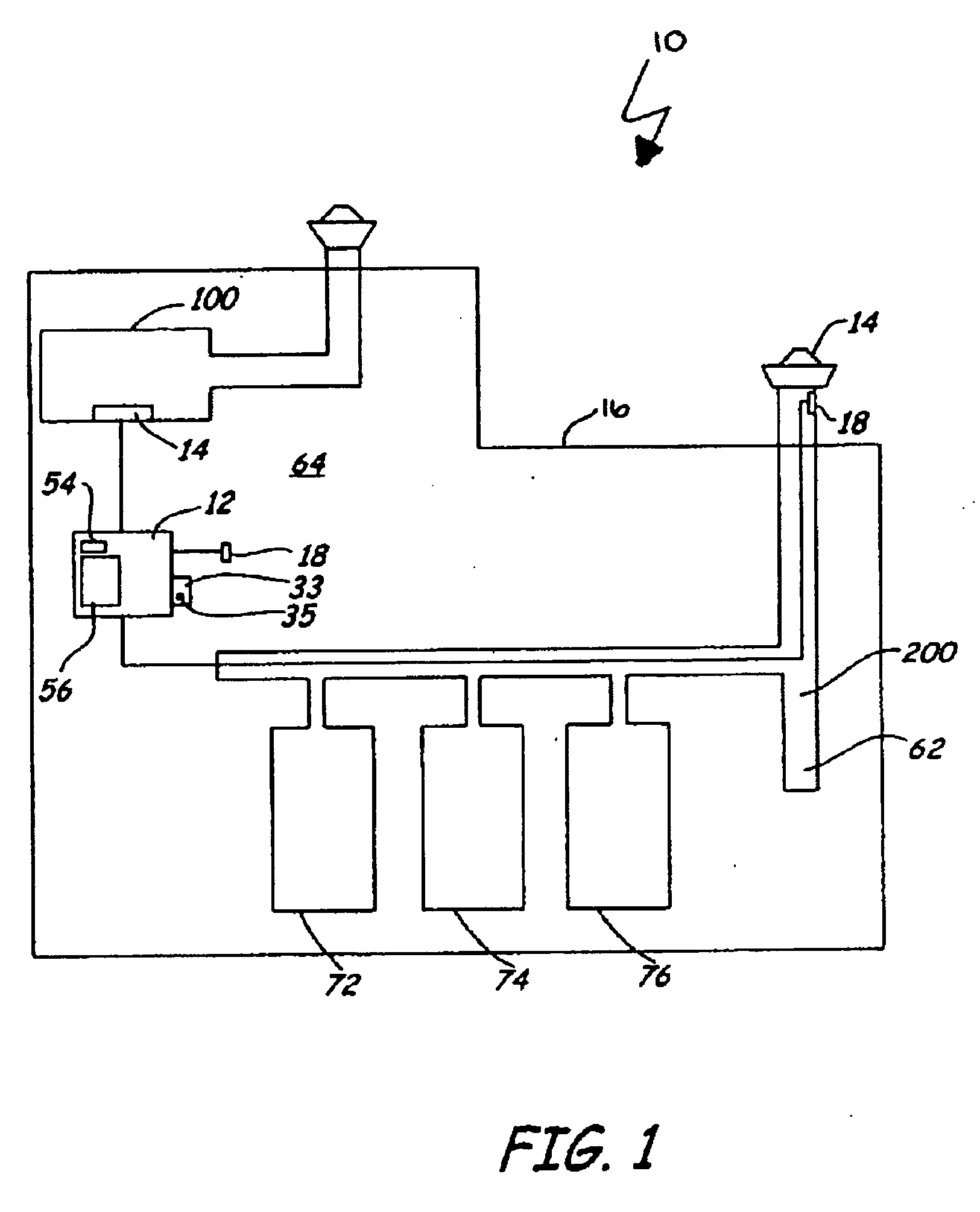
Yet another problem associated with boiler rooms is the presence of different types of appliances sharing a common exhaust
flue or combustion air system.
Conventional controllers are typically limited to controlling one type of appliance, such as boilers, furnaces, water heaters, etc.
However, other appliances that operate independently have an
impact on the flow through the air system.
Often, the response of the air control system is insufficient to prevent
overdraft or back-draft conditions that can result in emergency shut-down of all equipment sharing the air system.

