Input device

a technology of input device and touch panel, which is applied in the field of input device, can solve the problems of difficult to know whether an object such as a user's finger or an input pen is simply placed on a touch panel, or whether, input errors

Inactive Publication Date: 2006-03-09
KK TOSHIBA
View PDF9 Cites 44 Cited by
  • Summary
  • Abstract
  • Description
  • Claims
  • Application Information

AI Technical Summary

Benefits of technology

[0010] According to a first aspect of the embodiment of the invention, there is provided an input device including: a display unit indicating an image of an input unit; a contact position detecting unit detecting a position of an object brought into contact with a contact detecting layer provided on a display layer of the display unit; a contact strength detecting unit detecting contact strength of the object brought into contact with the contact detecting layer; and a contact state determining unit which extracts a feature quantity of the detected contact strength, compares the extracted feature quantity with a predetermined threshold, and determines a contact state of the object.

Problems solved by technology

Up to now, it is however very difficult to know whether an object such as a user's finger or an input pen is simply placed on a touch panel or whether the touch panel is depressed by such an object.
This tends to lead to input errors.

Method used


Image

  • Input device
  • Input device
  • Input device

Examples


first embodiment

[0055] In this embodiment, the invention relates to an input device, which is a kind of an input-output device of a terminal unit for a computer.

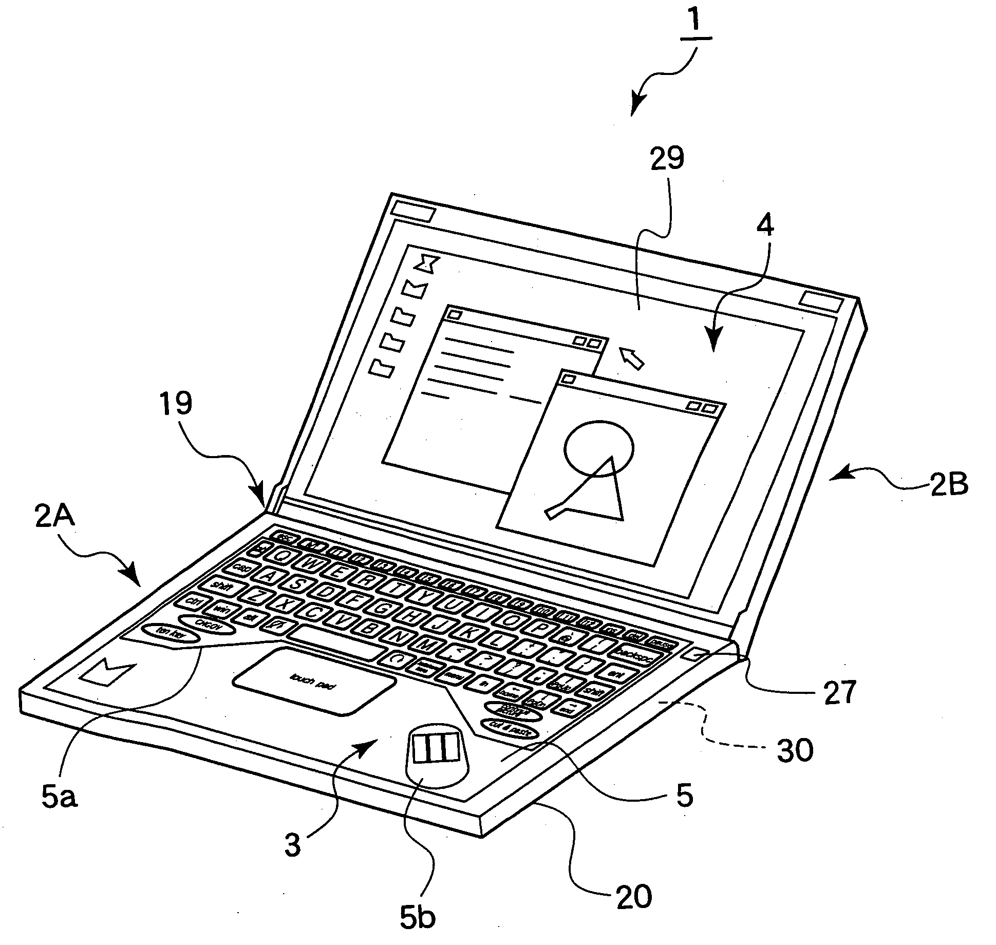
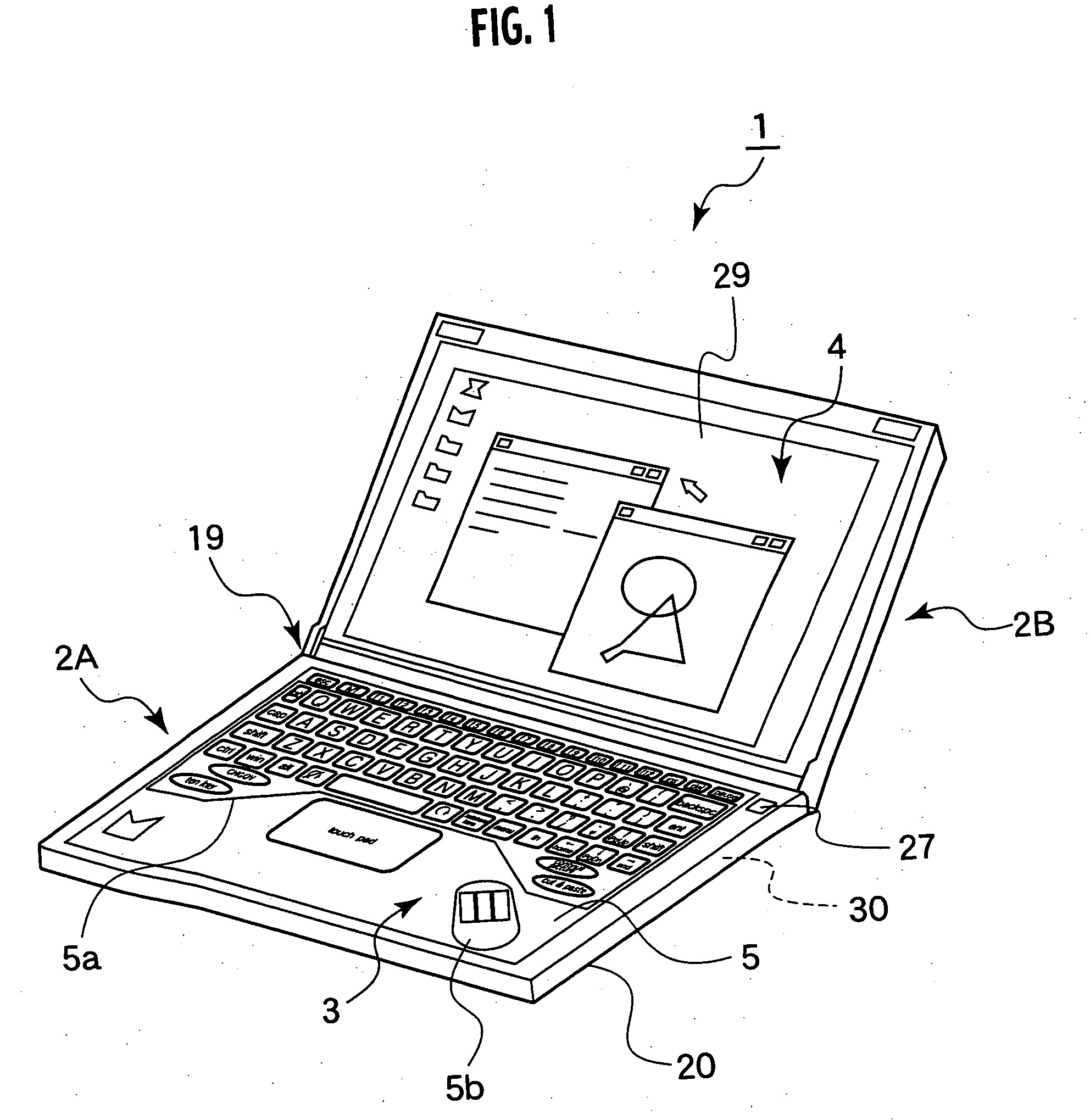
[0056] Referring to FIG. 1, a portable microcomputer 1 (called the “microcomputer 1”) includes a computer main unit 30, a lower housing 2A and an upper housing 2B. The computer main unit 30 includes an arithmetic and logic unit such as a central processing unit. The lower housing 2A houses an input unit 3 as a user interface for the computer main unit 30. The upper housing 2B houses a display unit 4 with a liquid crystal display panel 29 (called the “display panel 29”).

[0057] The computer main unit 30 uses the central processing unit in order to process information received via the input unit 3. The processed information is indicated on the display unit 4 in the upper housing 2B.

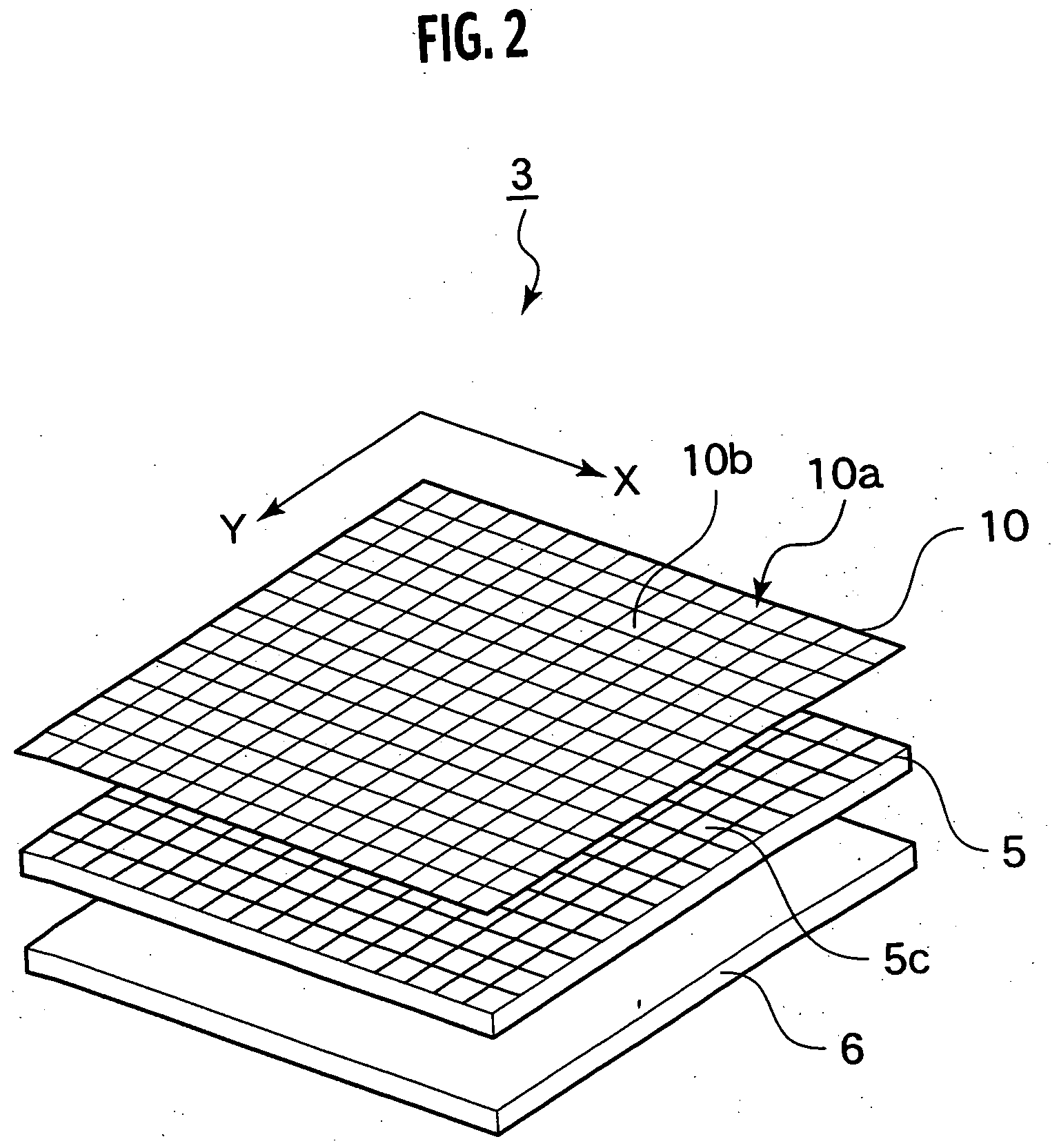
[0058] The input unit 3 in the lower housing 2A includes a display unit 5, and a detecting unit which detects a contact state of an object (such as a user's fing...

second embodiment

[0184] In this embodiment, the display unit 5 shows the virtual keyboard as the input device. An input device 60 detects whether keys are hit by a user's right or left hand.

[0185] Referring to FIG. 24, the input device 60 includes a touch panel 10, display unit 5, and backlight 6. The touch panel 10 includes a detecting layer 10a and a resistance detecting layer 65 on the detecting layer 10a. The touch panel 10, display unit 5 and backlight 6 are the same as those in the first embodiment, and will not be described here.

[0186] Referring to FIG. 25, the resistance detecting layer 65 includes: key detecting elements 66 corresponding to the positions of the keys on the virtual keyboard; a left palm detecting electrode 68a; and a right palm detecting electrode 68b, all of which are arranged on a printed wiring pattern made of a transparent conductive film. The transparent conductive film is structured similarly to those generally used for a variety of displays such as LCD. The resistan...


PUM


Abstract

An input device includes: a display unit indicating an image of an input position; a contact position detecting unit detecting a position of an object brought into contact with a contact detecting layer provided on a display layer of the display unit; a contact strength detecting unit detecting contact strength of the object brought into contact with the contact detecting layer; and a contact state determining unit which extracts a feature quantity of the detected contact strength, compares the extracted feature quantity with a predetermined threshold, and determines a contact state of the object.

Description

CROSS REFERENCE TO RELATED APPLICATIONS [0001] This application is based upon and claims the benefit of priority from prior Japanese Patent Application 2004-239872 filed on Aug. 19, 2004; the entire contents of which are incorporated by reference herein. BACKGROUND OF THE INVENTION [0002] 1. Field of the Invention [0003] The present invention relates to an input device which feeds information into a computer or the like, a computer provided with the input device, and information processing method and program. [0004] 2. Description of the Related Art [0005] Usually, an interface for a computer terminal includes a keyboard and a mouse as an input device, and a cathode ray tube (CRT) or a liquid crystal display (LCD) as a display unit. [0006] Further, so-called touch panels in which a display unit and an input device are laminated one over another are in wide use as interfaces for computer terminals, small portable tablet type calculators, and so on. [0007] Japanese Patent Laid-Open Pu...

Claims


Application Information

Patent Timeline
Patent Type & Authority Applications(United States)
IPC IPC(8): G09G5/00G06F3/041
CPCG06F1/1616G06F1/1637G06F1/1647G06F1/169G06F3/0213G06F3/04883G06F3/041G06F3/0418G06F3/045G06F3/0488G06F3/03547G06F3/0421
Inventor OZAWA, MASANORIHISANO, KATSUMIFURUKAWA, RYOMUKAI, MINORU
Owner KK TOSHIBA
Why Eureka
Try Eureka