Walking assistance device provided with a force sensor

a technology of force sensor and assistance device, which is applied in the field can solve the problems of inconvenient fastening and unfastening of such a belt, limited information provided by sensors for the control of walking assistance device, and user discomfort, so as to facilitate the effort required, facilitate the wearing of the retaining member of the thigh, and facilitate the effect of force being effectively transmitted to the thigh

Inactive Publication Date: 2006-03-09
HONDA MOTOR CO LTD
View PDF4 Cites 63 Cited by
  • Summary
  • Abstract
  • Description
  • Claims
  • Application Information

AI Technical Summary

Benefits of technology

[0009] A second object of the present invention is to provide a walking assistance device including a force sensor which would not hamper the movement of the user.
[0019] To facilitate the wearing of the thigh retaining member to the thigh of the wearer and, at the same time, to securely keep the thigh retaining member on the thigh of the wearer, a width W1 of a space between free ends of the arms is smaller than an inner diameter W2 of the thigh retaining member in a natural state of the thigh retaining member.

Problems solved by technology

Therefore, the belt has to be securely fastened around the thigh for an accurate measurement, but this prevents free movements of the muscles of the thigh, and causes a discomfort to the user.
This prior art also includes force sensors placed under the sole of each foot, but these sensors provide limited information for the control of the walking assistance device.
Typically, the transmitted force concentrates at the point of connection between the fastening belt and thigh support member so that the adjacent part of the thigh is subjected to a localized force, and this is detrimental in transmitting a large force to the thigh and preventing discomfort to the user.
Also, the fastening and unfastening of such a belt is not convenient particularly because the fastening belt must be tautly applied to the thigh of the user and this requires a significant amount of effort.

Method used


Image

  • Walking assistance device provided with a force sensor
  • Walking assistance device provided with a force sensor
  • Walking assistance device provided with a force sensor

Examples


Embodiment Construction

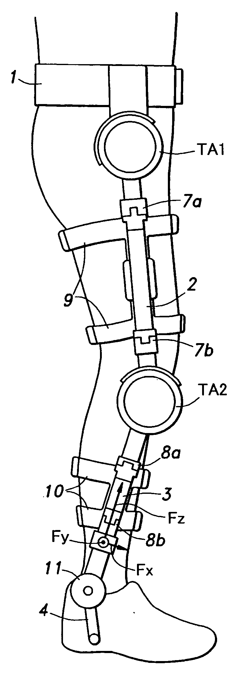
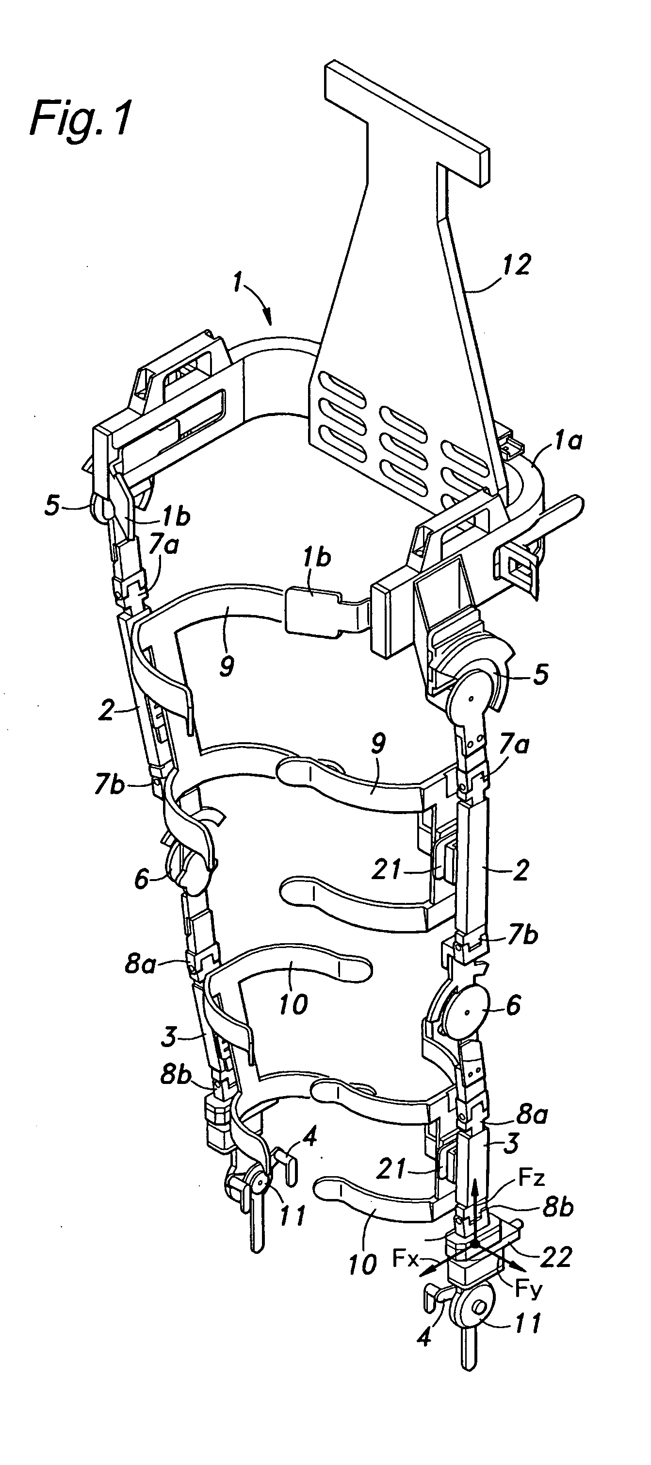
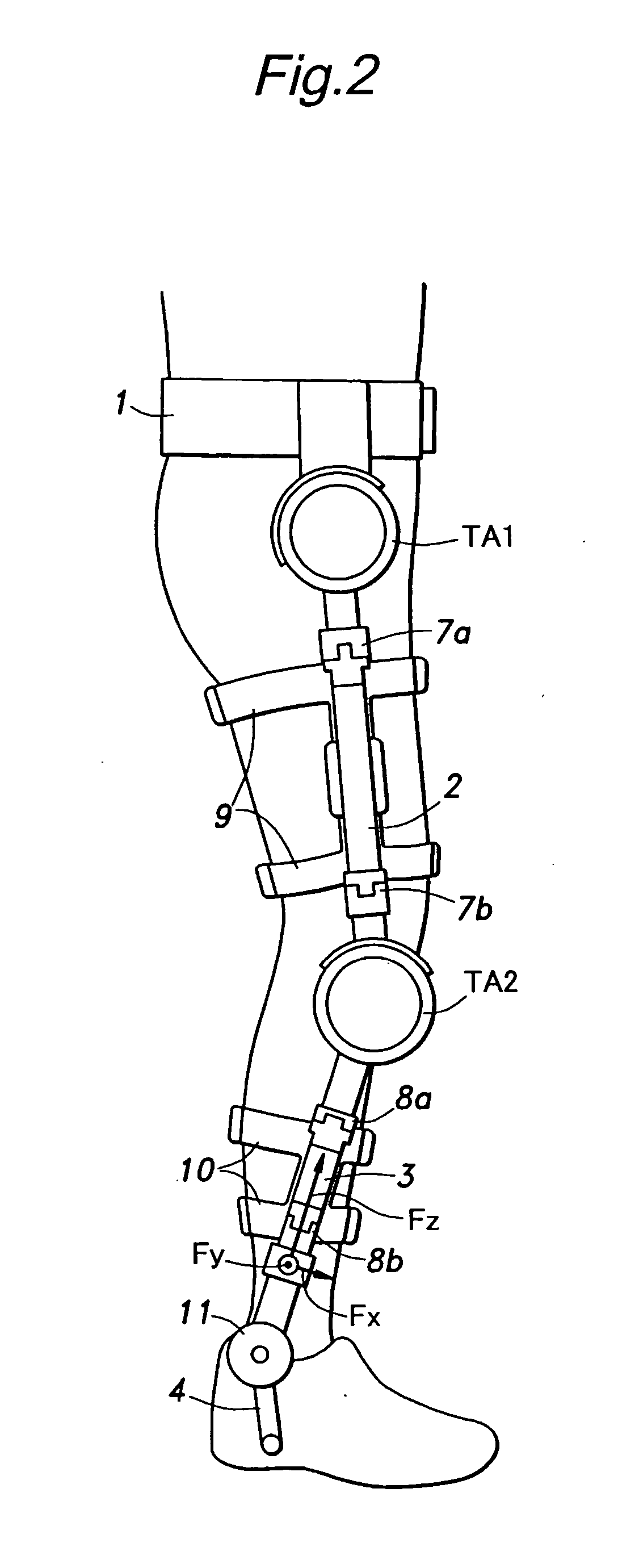
[0029]FIG. 1 is an overall perspective view of an exoskeltal walking assistance device embodying the present invention, and FIG. 2 is a side view showing the walking assistance device when worn by a user. As shown in FIG. 1, the walking assistance device comprises a pelvis support member 1 adapted to be worn on the pelvis of the user, a thigh support member 2 which is vertically elongated so as to be placed on the outer side part of each thigh of the user, a leg support member 3 adapted to be placed on the outer part of each leg of the user, and a foot support member 4 adapted to be engaged by the shoe worn on each foot of the user. The “thigh” as used herein means a part of the limb extending between the hip joint and knee joint, and the “leg” as used herein means a part of the limb extending between the knee joint and ankle.

[0030] As shown in FIG. 3, the pelvis support member 1 includes a base portion 1a made of a relatively rigid material and provided with the shape of letter-U ...


PUM


Abstract

In walking assistance device, a force detector (21) is provided between thigh retaining member (9) that directly retain the thigh of the user and a thigh support member (2) that is actuated by an actuator (TA1) provided in hip coupling portion. Thereby, the load acting on the hip coupling portion can be accurately detected, and the output of the force detector can be favorably used for the purpose of controlling the actuator so as to minimize the force that is applied to the thigh of the user. In particular, to the end of providing a suitably rigidity to the thigh retaining member so that the force produced by the actuator may be evenly applied to the entire thigh, and facilitating the effort required for the wearer to wear the walking assistance device, the thigh retaining member comprises a base portion (9a) connected to the thigh support member and two pairs of resilient arms (9b, 9c) extending laterally from either side of the base portion so that the thigh retaining member generally defines a shape of letter-C in plan view.

Description

TECHNICAL FIELD [0001] The present invention relates to a walking assistance device including a force sensor provided between a member for retaining a thigh or leg of a user and the corresponding support member of the device so that the output signal from the force sensor may be used for the control of the device in a favorable manner. BACKGROUND OF THE INVENTION [0002] Various muscle assistance devices have been proposed as can be found in Japanese patent laid open publications No. 2003-250844 and No. 7-163607, for instance, for the purpose of providing an assisting force to the movement of the leg by using a toque actuator consisting of an electric motor or the like attached to a side part of the hip or knee joint. For instance, such a muscle assistance device enables a person caring a bedridden person to produce a force of the leg which is substantially greater than that the person is normally capable of producing or a person having a walking impediment owing to aging or the like...

Claims


Application Information

Patent Timeline
Patent Type & Authority Applications(United States)
IPC IPC(8): A61F5/00
CPCA61F5/0102
Inventor SHIMADA, KEIHIRATA, TAKASHIASHIHARA, JUNNODA, TATSUYAIKEUCHI, YASUSHI
Owner HONDA MOTOR CO LTD
Why Eureka
Try Eureka