Bone dust accumulator

a technology of bone dust and accumulator, which is applied in the field of bone dust accumulator, can solve the problems of difficult and/or expensive manufacture, complicated apparatus, and difficult use,

a technology of bone dust and accumulator, which is applied in the field of bone dust accumulator, can solve the problems of difficult and/or expensive manufacture, complicated apparatus, and difficult use,

US20060052760A1Inactive Publication Date: 2006-03-09BATZDORF ULRICH

Image

  • Bone dust accumulator
  • Bone dust accumulator
  • Bone dust accumulator

Examples


Embodiment Construction

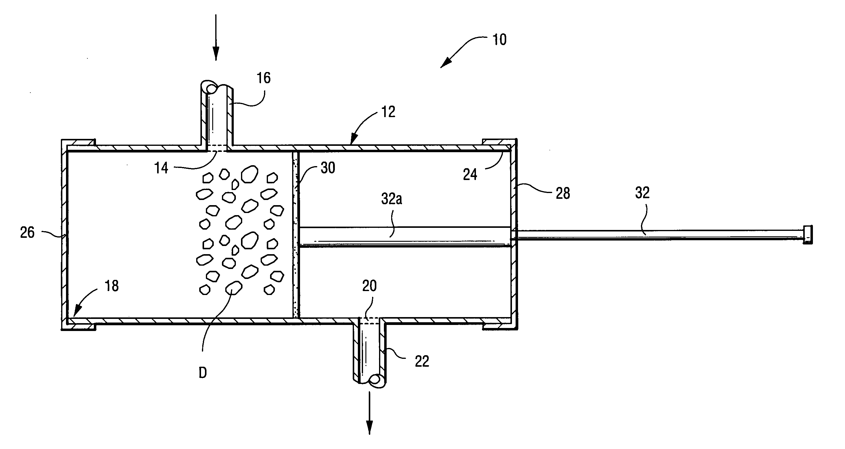
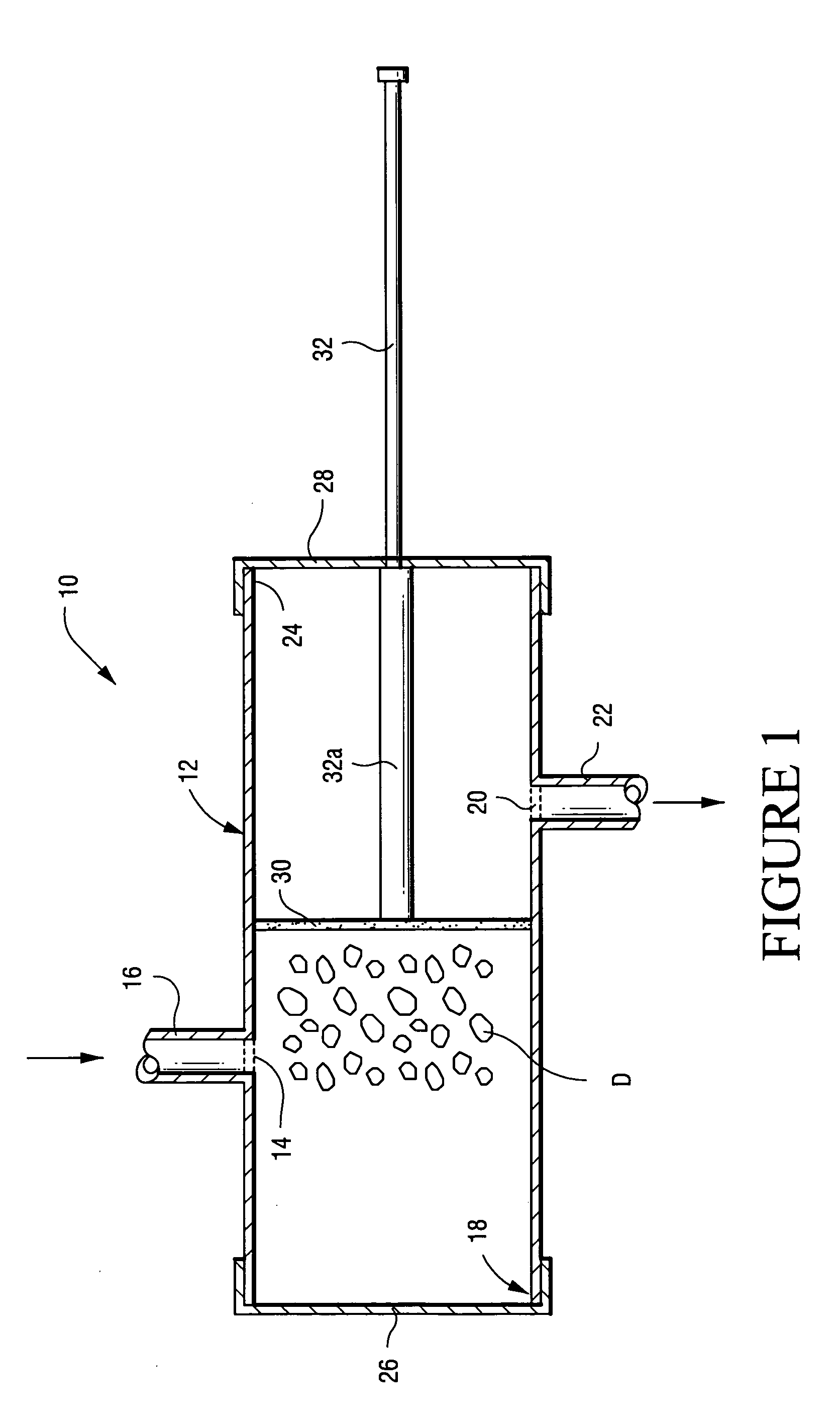
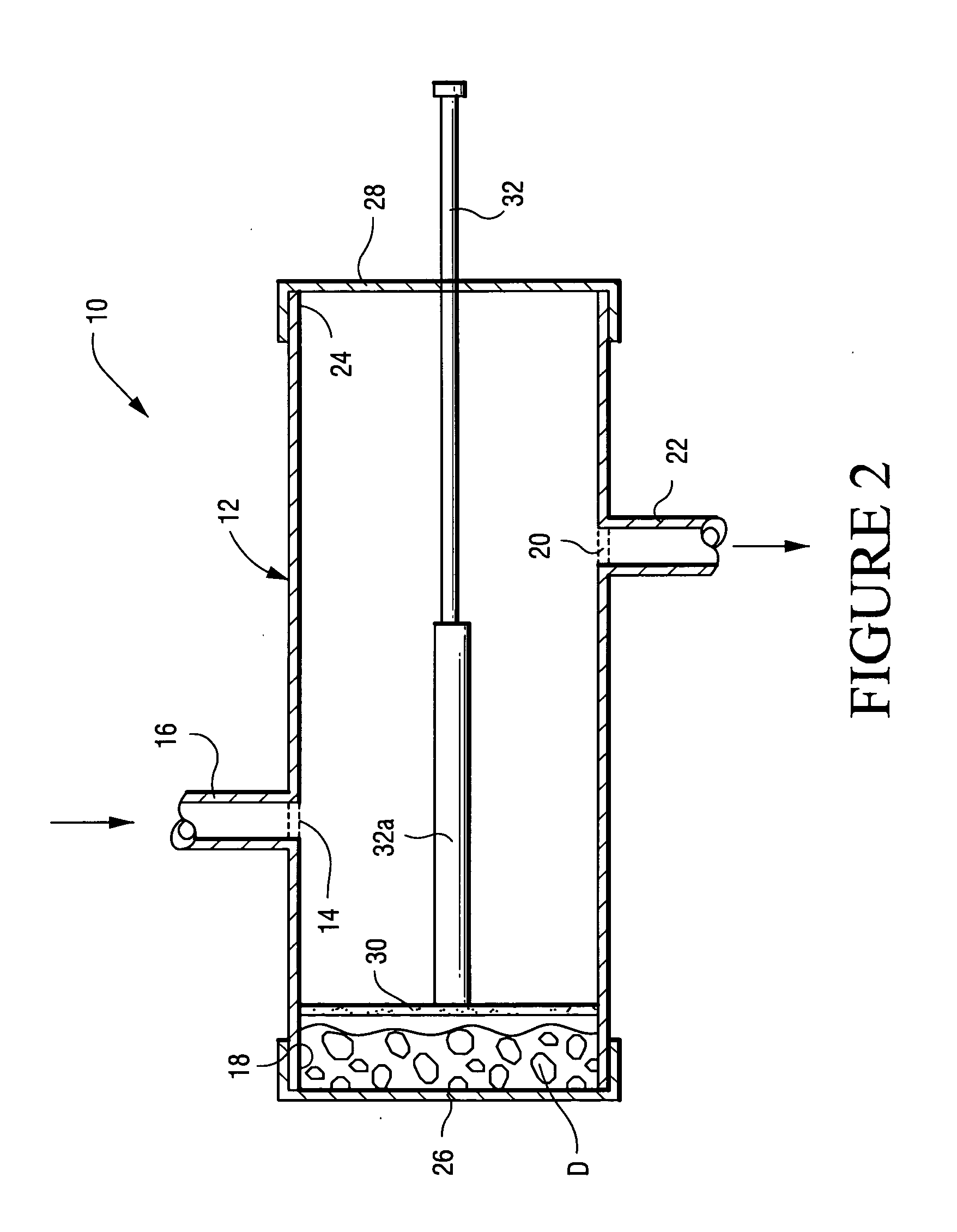
[0019] Referring to FIG. 1, the bone dust accumulator apparatus 10 of the present inventions comprises a collecting vessel 12 of any suitable construction and formed of any suitable material, such as metal or plastic. As an illustrative example, the vessel 12 may be of elongated, cylindrical construction. The vessel 12 may be treated in any appropriate manner so as to be sterile.

[0020] The collecting vessel 12 comprises an inlet opening 14 and inlet tube 16 near one end 18 thereof, and an outlet opening 20 and outlet tube 22 near the opposite end 24 thereof. The one end 18 of the vessel 12 is closed by an end closure 26 of any suitable construction which may be movably mounted on one end 18 to open and close it, or may be removably mounted thereon for the opening and closing thereof. The opposite end 24 of the vessel 12 is closed by an end closure 28 of any suitable construction.

[0021] A plunger 30 formed of a suitable permeable material, e.g., a biologically inert plastic, such a...


PUM


Abstract

A method and apparatus for accumulating bone dust in a fluid from a surgical site or the like, wherein a collecting vessel is provided that has an inlet opening near one end thereof and an outlet opening near the opposite end thereof. A permeable plunger is slidably mounted in the vessel for movement between a first position wherein it is disposed between the inlet opening and the outlet opening, and a second position wherein it is disposed near the one end of the vessel. Fluid containing bone dust from a surgical site is conveyed through the inlet opening into the vessel when the plunger is in the first position, such that the fluid passes through the plunger and through the outlet opening. The plunger is of a construction to prevent the bone dust from passing therethrough such that it is accumulated between the plunger and the one end of the vessel. When sufficient bone dust is accumulated, the plunger is moved to the second position to move the accumulated bone dust toward the one end of the vessel for removal therefrom.

Description

[0001] This application claims the priority of U.S. Provisional Application No. 60 / 603,010, filed on Aug. 20, 2004.BACKGROUND OF THE INVENTION [0002] 1. Field of the Invention [0003] The present invention relates to a method and apparatus for collecting bone dust which is generated by the drilling of bone during an operation or the like and, more particularly, to such a method and apparatus wherein the accumulated bone dust can be used as part of the bone materials for bone fusion or other purposes. [0004] 2. Description of Related Art [0005] Many surgical procedures are performed which involve drilling away bone as, for example, for decompression of the spinal cord or nerve roots, as well as in the preparation of other bones in the body for fusion or other purposes. High-speed drills, burrs or other tools are generally employed for this purpose, and the bone dust so generated is usually suctioned off together with irrigating fluid and discarded. Once the preparation of the bone has...

Claims


Application Information

Patent Timeline
09 Mar 2006
Publication
US20060052760A1
IPC
A61M1/00
CPC
A61B17/16; A61F2/4644; A61M1/0056; A61F2002/4685; A61F2002/4646; A61M1/79
Inventors
BATZDORF, ULRICH