Surgical clamp and cutting blade

Inactive Publication Date: 2006-03-09
THOMPSON SURGICAL INSTR
View PDF18 Cites 197 Cited by
  • Summary
  • Abstract
  • Description
  • Claims
  • Application Information

AI Technical Summary

Benefits of technology

[0010] The present invention is directed to a surgical clamp and cutting device, and more particularly, to a surgical clamp for use in grasping stainless steel wire sutures typically used to repair the sternum after open heart surgery. T

Problems solved by technology

The short section of wire protruding from the needle end is sharp and may often times tear the surgeon'

Method used


Image

  • Surgical clamp and cutting blade
  • Surgical clamp and cutting blade
  • Surgical clamp and cutting blade

Examples


Embodiment Construction

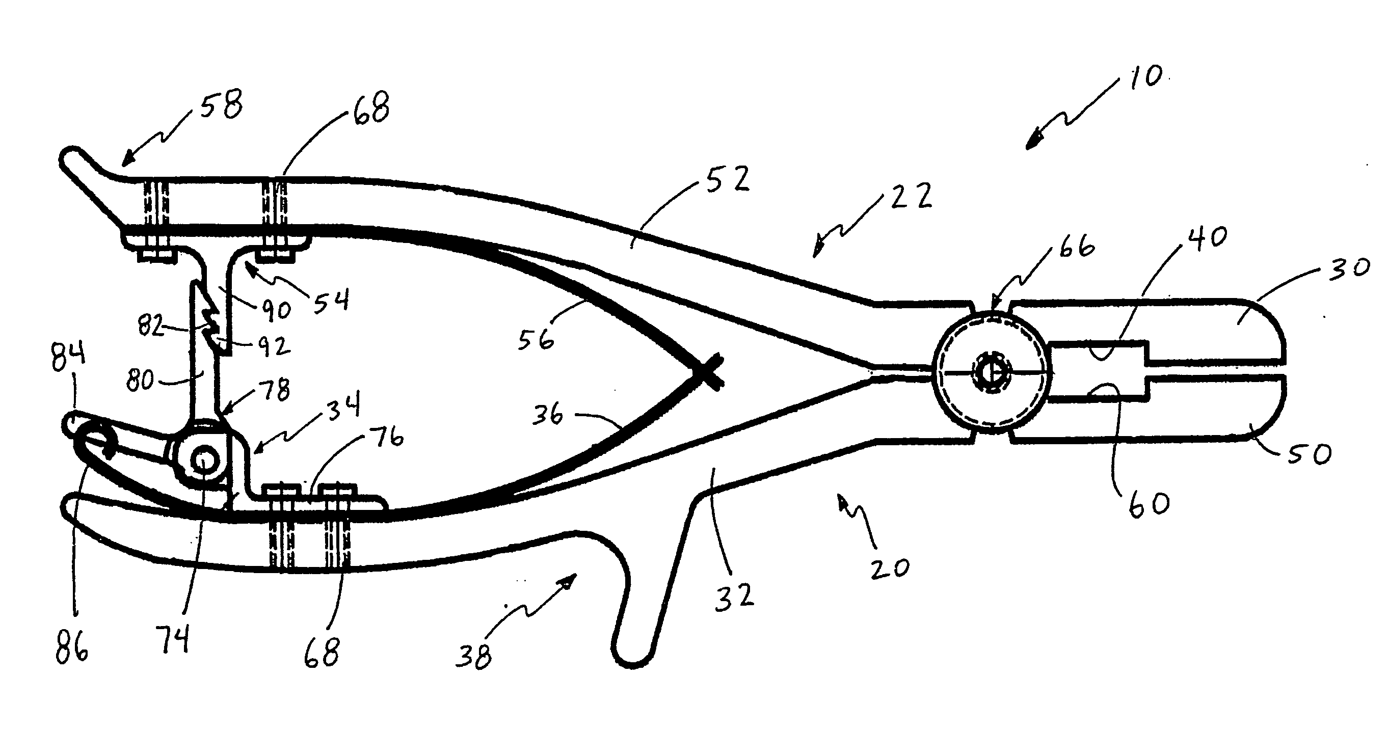
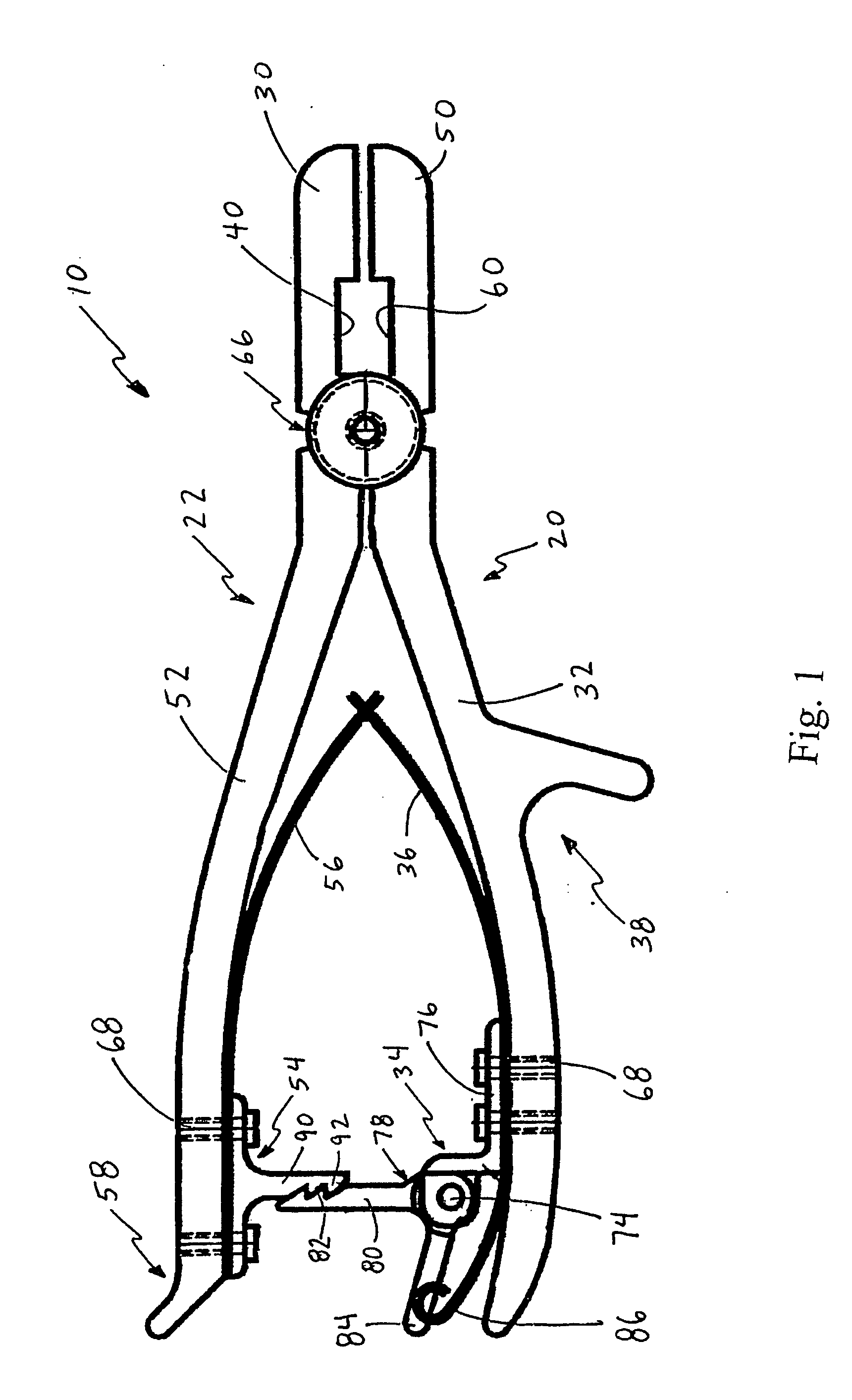
[0018]FIG. 1 is an elevated, partial cross-sectional view of a surgical clamp 10 of the present invention. The surgical clamp 10 has a first member 20 and a second member 22.

[0019] The first member 20 includes a first member jaw 30, a first member handle 32, a first member locking component 34, a first member spring component 36, a first member hand seat 38, and a first member slot 40 positioned within the jaw 30. The second member 22 includes a second member jaw 50, a second member handle 52, a second member locking component 54, a second member spring component 56, a second member little finger seat 58, and a second member slot 60 located within the second member jaw 50.

[0020] The first member 20 and the second member 22 are pivotally connected at pivot 66 in a manner conventionally used for prior art surgical clamps. The locking component 34 and the spring component 36 are fixedly attached to the handle 32 of the first member 20 by conventional screws 68. Handle 32 will have ap...


PUM


Abstract

A surgical clamp includes a first member having a first handle, a first jaw, and a first pivot point intermediate the first handle and the first jaw; a second handle member having a second handle, a second jaw, and a second pivot point intermediate the second handle and the second jaw. The second handle member is pivotally connected to the first handle member at their respective pivot points. The first jaw and the second jaw cooperate to define a clamping element and a cutting element.

Description

CROSS-REFERENCE TO RELATED APPLICATION [0001] None. STATEMENT REGARDING FEDERALLY-SPONSORED RESEARCH OR DEVELOPMENT [0002] None. BACKGROUND OF THE INVENTION [0003] The present invention relates to a surgical clamp and cutting device. More particularly, the present invention relates to a surgical clamp and cutting device for use in connection with a wire sternotomy suture. [0004] A sternotomy is an incision into or through the sternum and is typically part of the open heart surgery procedure. During such open heart surgery, the sternum is split to provide access to the inside of the patient's chest. After the surgery, the patient's sternum must be sutured back together. Typically, the sternum is sutured back together by passing a needle attached to a stainless steel wire through either side of the sternum, drawing the opposed sides of the sternum together so that the sternum may heal properly. In such a suturing procedure, it is typical to use a needle to lace the stainless steel wir...

Claims


Application Information

Patent Timeline
IPC IPC(8): A61B17/28
CPCA61B17/12013A61B17/122A61B17/29A61B17/282A61B17/2816
Inventor DRAKE, DANIEL H.MULAC, ANTHONY J.FARLEY, DANIEL K.
Owner THOMPSON SURGICAL INSTR
Why Eureka
Try Eureka