Brake element having integrated wear sensor

a technology of wear sensor and brake element, which is applied in the field of brake elements, can solve the problems of reducing increasing the cost and complexity of manufacturing and installing such brake elements, and affecting the use of brake elements, so as to simplify the manufacture of such brake elements and eliminate parts. , the effect of most us

Inactive Publication Date: 2005-08-11
FEDERAL MOGUL WORLD WIDE
View PDF12 Cites 5 Cited by
  • Summary
  • Abstract
  • Description
  • Claims
  • Application Information

AI Technical Summary

Benefits of technology

[0007] The invention has the advantage of eliminating parts by incorporating the wear sensor as an integral part of the backing plate.
[0008] The one piece construction of the backing plate and wear sensor further simplifies the manufacture of such brake elements since the steps of procuring, stocking, supplying and assembly an otherwise separate wear sensor clip is eliminated.
[0009] The one piece wear sensor construction has the further advantage of enabling precise positioning of the wear sensor tip end relative to the front face of the backing plate, and thus the depth of pad wear permitted before the wear sensor is exposed. This has the advantage of getting the most use out of the pads and having consistency from pad to pad.
[0010] The structure is much simpler since there is no need to fabricate a clip that has both wear sensor features and mounting features. According to a preferred embodiment, all that may be needed is a punch for displacing a portion of the backing plate out of the plane of the backing plate to yield a tab-like wear sensor projection.

Problems solved by technology

The separate clips can become lost or dislodged during shipping, installation and / or use and add to the cost and complexity of manufacturing and installing such brake elements.

Method used


Image

  • Brake element having integrated wear sensor
  • Brake element having integrated wear sensor

Examples


Embodiment Construction

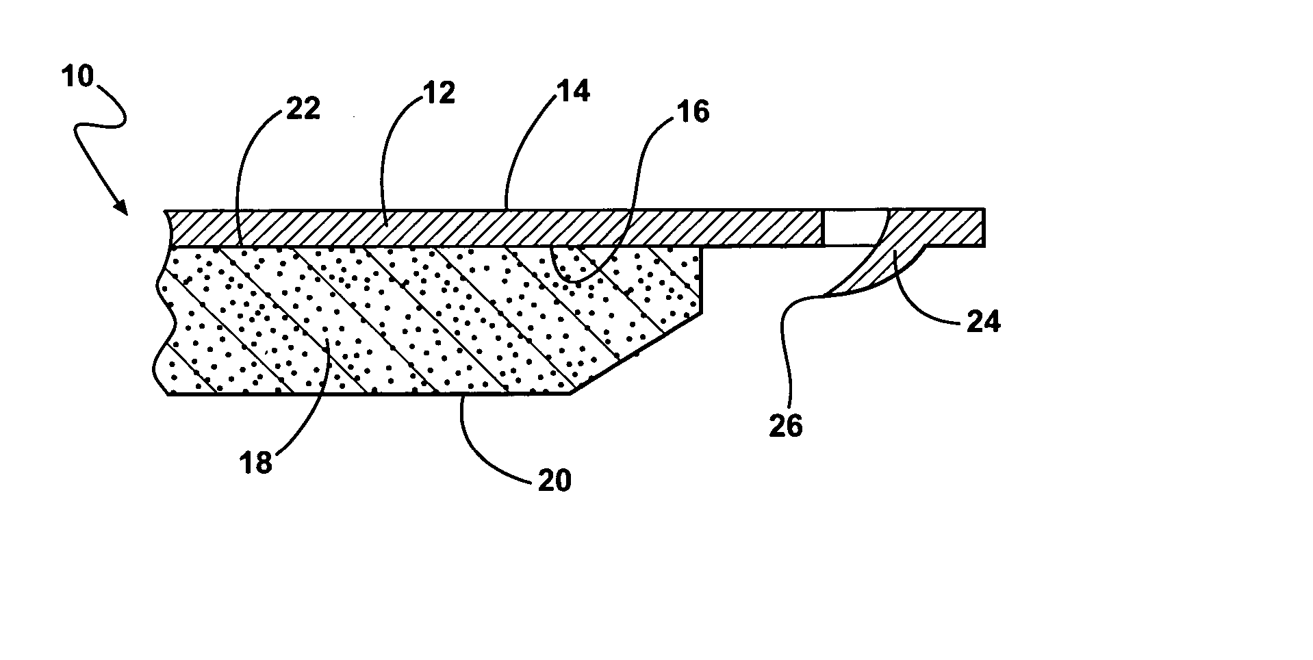
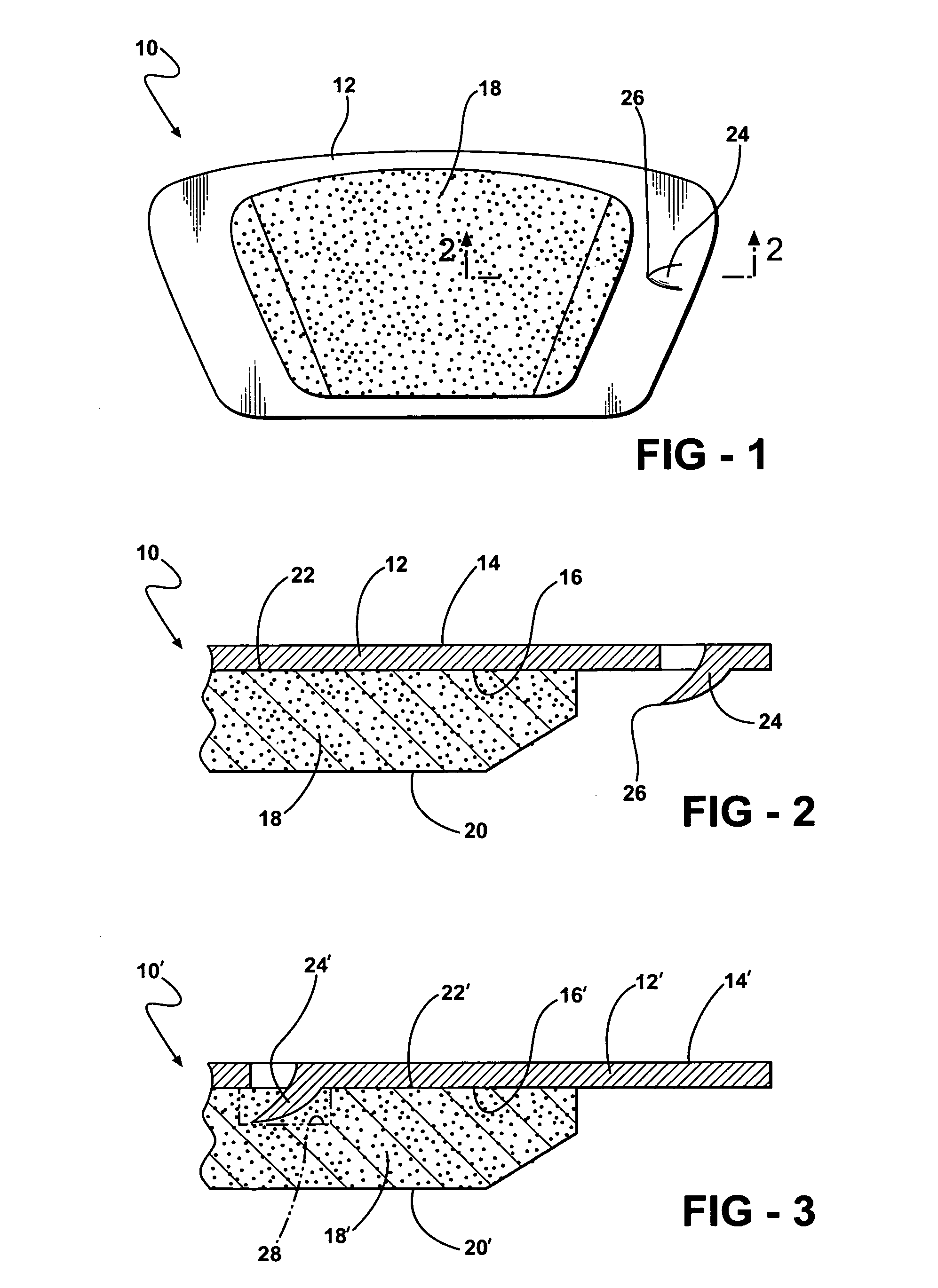
[0016] Disclosed in FIGS. 1 and 2 is a brake element 10 constructed according to a first embodiment of the invention having a steel backing plate 12 with a back surface 14 and a front surface 16. A pad 18 of friction material is mounted on the front surface 16. The pad 18 has a predetermined thickness between an outer braking surface 20 and in inner mounting surface 22 or the front surface 16.

[0017] The backing plate 12 is formed with an integrated wear sensor 24. The wear sensor 24 projects outwardly from the front surface 16 of the back plate 12 generally towards the outer braking surface 20 of the pad 18. The wear sensor 24 terminates at a tip end 26 spaced between the outer braking surface 20 and the mounting surface 22. According to the first embodiment, the wear sensor 24 is positioned adjacent to rather than embedded in, the friction pad 18. The wear sensor 24 is preferably punched as a tab from the body of the backing plate 12. The tab 24 may be formed prior to or after the...


PUM


Abstract

A brake element for use in applying a frictional braking force to a rotating brake rotor includes a backing plate and a pad of friction material mounted on the backing plate. The backing plate is formed with an integral wear sensor portion in the form of a punched tab feature that is bent out of the mounting plate. A tip end of the wear sensor resides below the level of the outer braking surface of the pad. When the pad wears to the point where the sensor tip is exposed, it rubs on the rotor and generates an audible signal.

Description

[0001] This application claims priority to U.S. Provisional Patent Application Ser. No. 60 / 481,670, filed Nov. 19, 2003.BACKGROUND OF THE INVENTION [0002] 1. Technical Field [0003] This invention relates generally to brake elements, and more particularly to those used in automotive brake application that are fitted with an audible wear sensor. [0004] 2. Related Art [0005] It is known in the art to attach a wear sensor clip or some other necgabucak device to the backing plate of a brake element. When the pad wears, the clip is exposed and rubs on the brake rotor to generate an audible signal which is meant to alert the operator to the worn condition of the brake elements. The separate clips can become lost or dislodged during shipping, installation and / or use and add to the cost and complexity of manufacturing and installing such brake elements. SUMMARY OF THE INVENTION [0006] A brake element constructed according to the present invention comprises a backing plate having a front surf...

Claims


Application Information

Patent Timeline
Patent Type & Authority Applications(United States)
IPC IPC(8): F16DF16D65/40F16D66/00F16D66/02
CPCF16D66/02
Inventor BUCKNER, GUY BRIAN
Owner FEDERAL MOGUL WORLD WIDE
Why Eureka
Try Eureka