Webbing retractor

a retractor and webbing technology, applied in the field of seatbelt systems, can solve the problem that the webbing belt cannot be completely pulled out of the spool

Active Publication Date: 2006-08-24
KK TOKAI RIKA DENKI SEISAKUSHO
View PDF14 Cites 4 Cited by
  • Summary
  • Abstract
  • Description
  • Claims
  • Application Information

AI Technical Summary

Benefits of technology

[0049] According to the above respective aspects, it is possible to eliminate the part of the webbing belt left in the spool in the entirely pulled-out state of the webbing belt.

Problems solved by technology

Namely, in the webbing retractor of such a structure, after assembly, the webbing belt cannot be entirely pulled out from the spool.

Method used


Image

  • Webbing retractor
  • Webbing retractor
  • Webbing retractor

Examples


Embodiment Construction

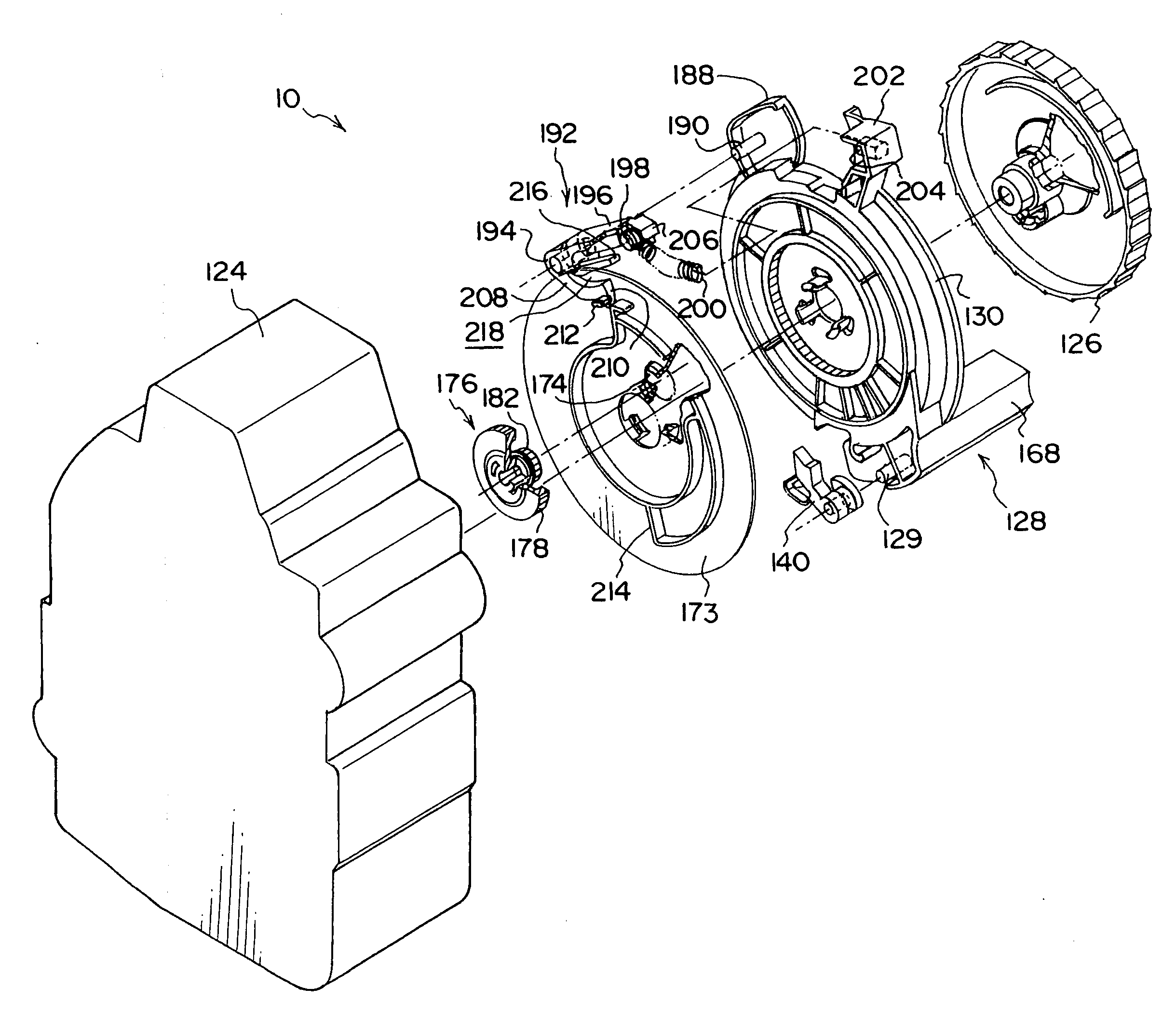
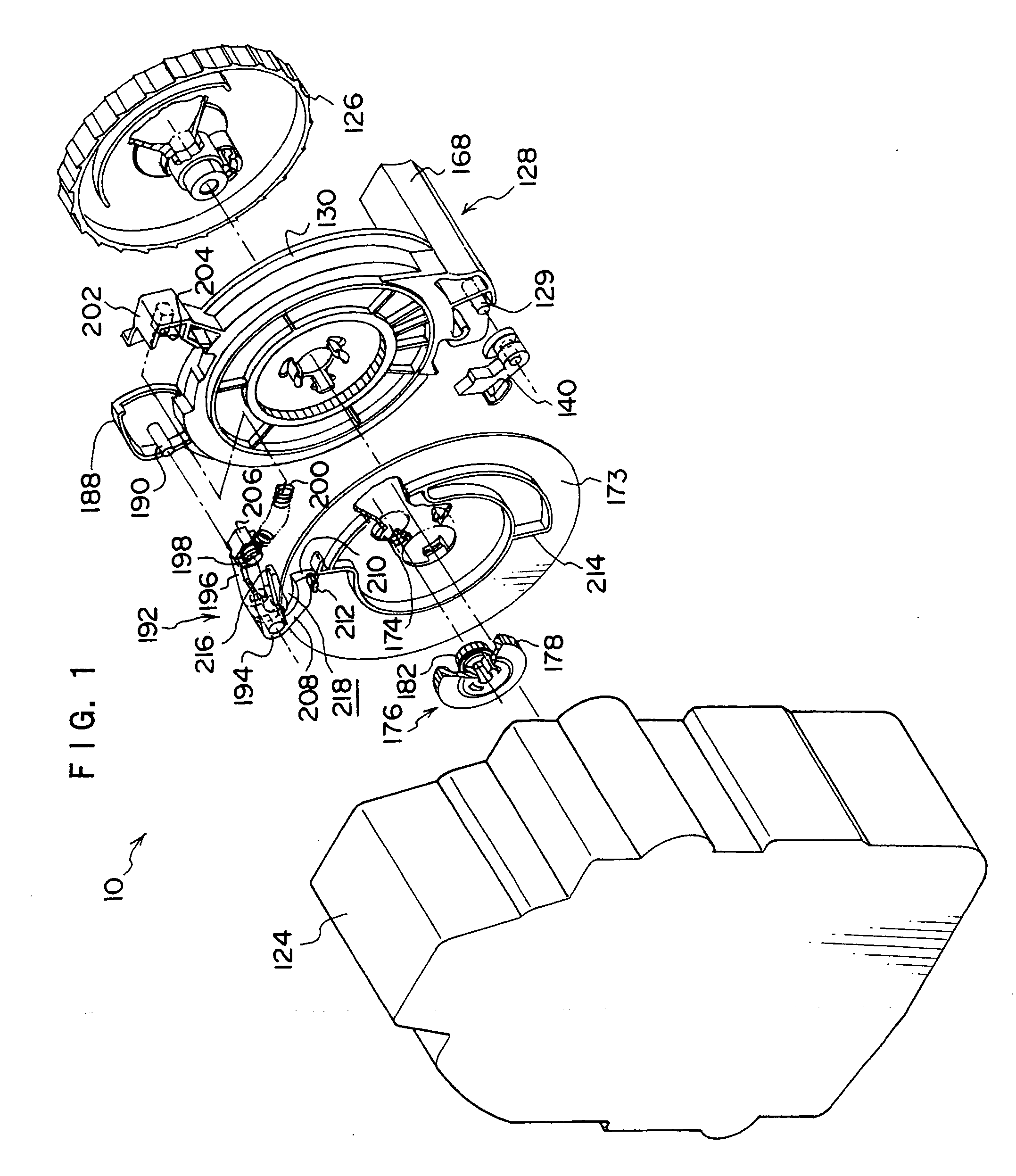
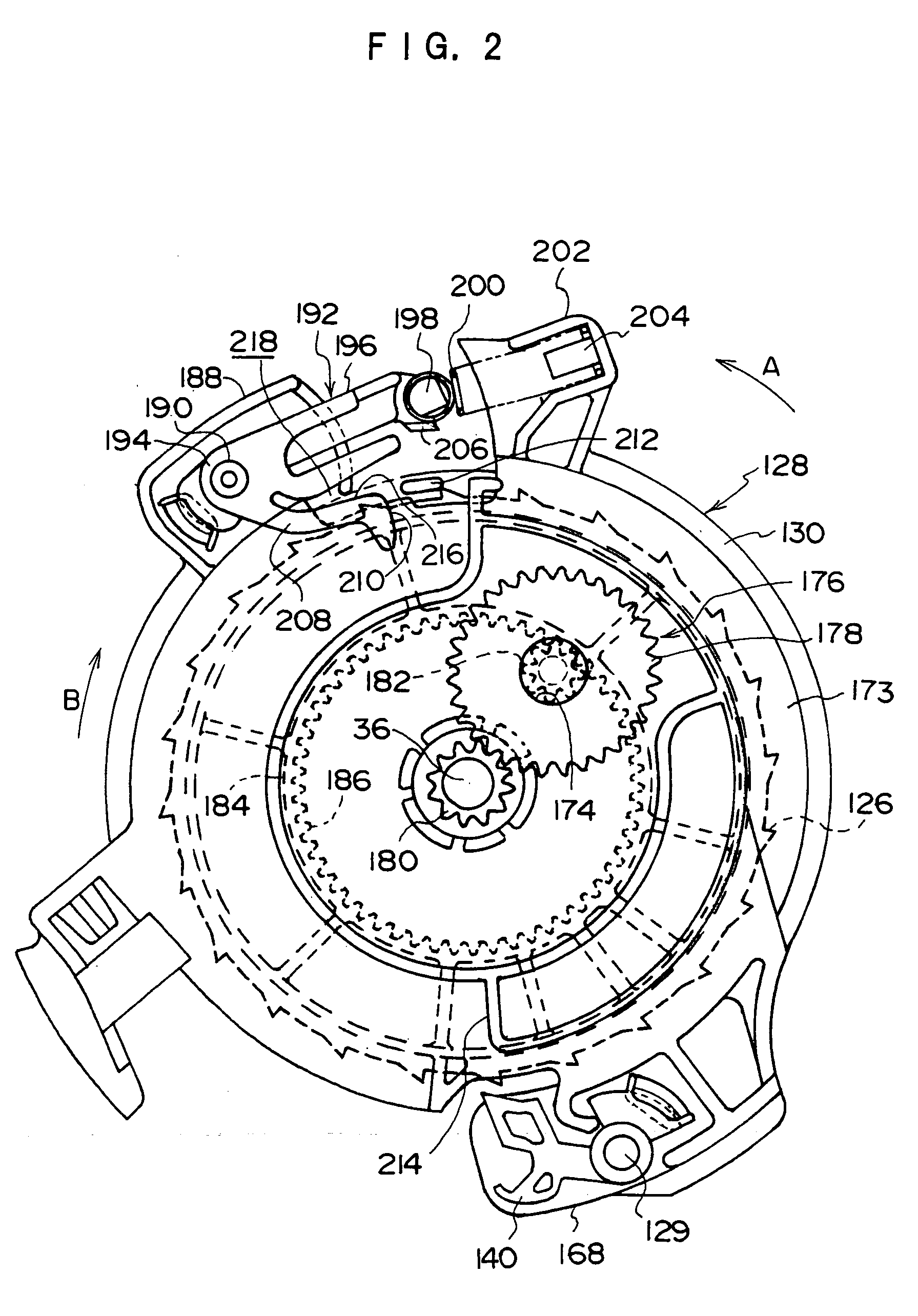
[0056] First, the overall structure of a webbing retractor 10 relating to an embodiment of the present invention will be described.

[0057] The overall structure of the webbing retractor 10 is summarily shown in an exploded perspective view in FIG. 6.

[0058] The webbing retractor 10 has a frame 12. The frame 12 has a plate-shaped back plate 14 whose direction of thickness runs substantially along the left-right direction of the vehicle. The webbing retractor 10 is mounted to a vehicle body due to the back plate 14 being fixed to a vicinity of the lower end portion of the center pillar of the vehicle body by a fastening means such as bolts or the like for example.

[0059] A leg plate 16 is formed by being bent inwardly in the transverse direction of the vehicle (the substantially left-right direction of the vehicle) from one transverse direction end of the back plate 14 provided along the substantially longitudinal direction of the vehicle. A leg plate 18 is formed by being bent in the...


PUM


Abstract

A webbing retractor is provided that enables elimination of the part of a webbing belt left in the spool in an entirely pulled-out state of a webbing belt. A space portion is formed in a notched shape in an ALR switch lever. A cam projection of a cam plate that presses the ALR switch lever and changes it to the engaging direction side to a spool enters into the inside of the space portion and, thereby, the cam projection can rotate to an advanced position at the cam pull-out direction side with respect its contact position with the ALR switch lever, whereby the webbing belt can be pulled out entirely.

Description

CROSS-REFERENCE TO RELATED APPLICATION [0001] This application claims priority under 35 USC 119 from Japanese Patent Application No. 2005-1723, the disclosure of which is incorporated by reference herein. BACKGROUND OF THE INVENTION [0002] 1. Field of the Invention [0003] The present invention relates to a seatbelt system for restraining bodies of vehicle occupants, and more specifically to a webbing retractor of a long strip-shaped webbing belt. [0004] 2. Description of the Related Art [0005] In a long strip-shaped webbing belt structuring a seatbelt system for a vehicle, a longitudinal base end thereof is engaged to a spool of a webbing retractor. When the spool is rotated in a take-up direction that is one direction around its own axis, the webbing belt is taken up and stored by the spool. [0006] In this kind of a webbing retractor, a lock mechanism that regulates the rotation of the spool in a pull-out direction that is opposite to the take-up direction and thereby limits the pu...

Claims


Application Information

Patent Timeline
Patent Type & Authority Applications(United States)
IPC IPC(8): B60R22/36
CPCB60R22/415
Inventor TAKAMATSU, HITOSHI
Owner KK TOKAI RIKA DENKI SEISAKUSHO
Why Eureka
Try Eureka