Handgun disassembly device

Inactive Publication Date: 2006-03-16
SHOBER DAVID R
View PDF2 Cites 10 Cited by
  • Summary
  • Abstract
  • Description
  • Claims
  • Application Information

AI Technical Summary

Benefits of technology

[0012] The device may be used on combination with a barrel pin removal tool. The pin removal tool includes a protrusion having a diameter sufficiently small to fit through a drift hole in the slide. The drift hole aligns with the barrel pin when the hand

Problems solved by technology

Despite the advantages of handgun designs having smooth outer surfaces, routine maintenance of such handguns, including their assembly and disass

Method used


Image

  • Handgun disassembly device
  • Handgun disassembly device
  • Handgun disassembly device

Examples


Example

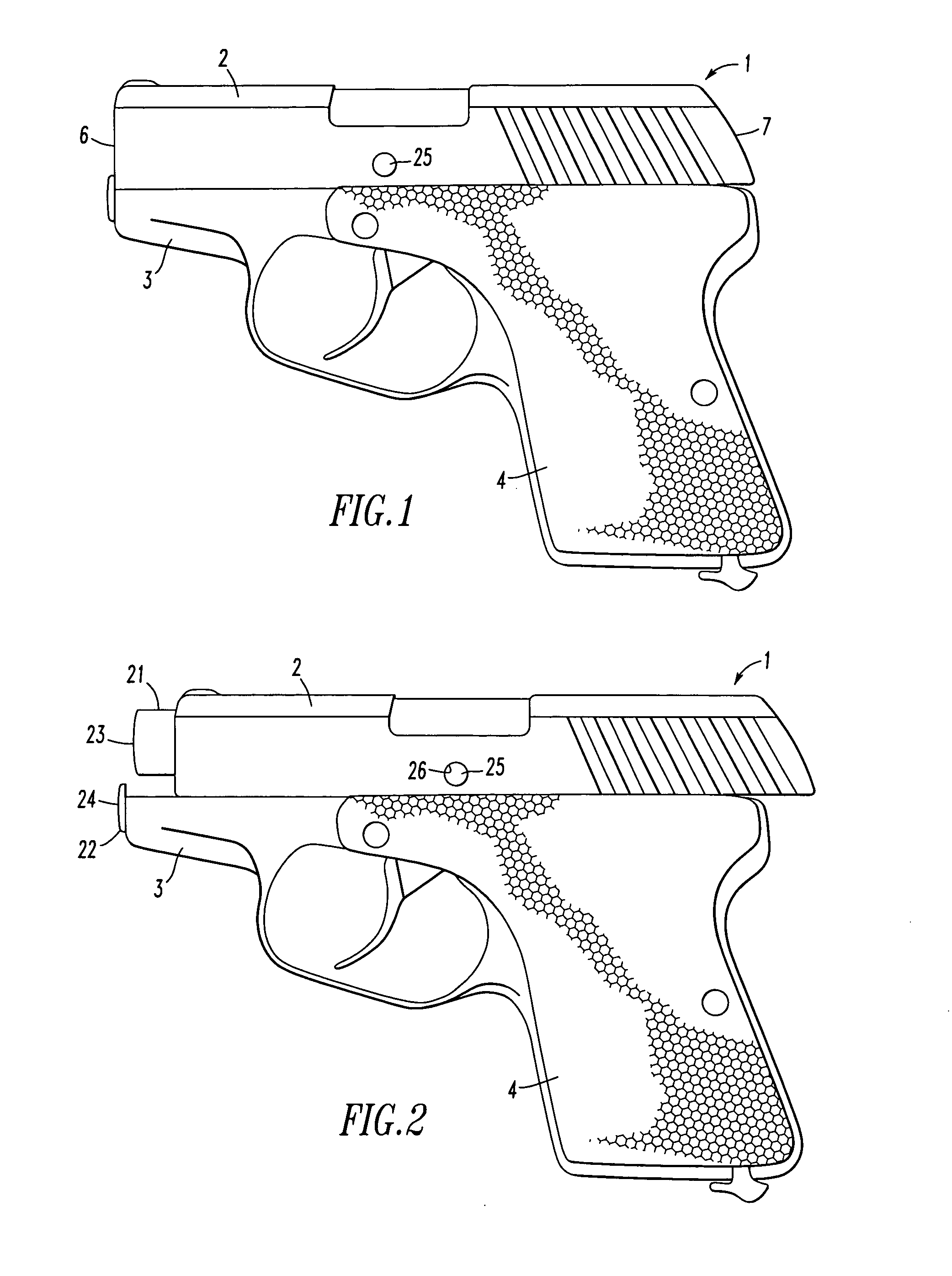
[0019]FIG. 1 shows an obverse side of a handgun of the Rohrbaugh design. The handgun 1 includes a slide 2, a frame 3, and a grip 4, a front end 6 and a rear end 7. The slide 2 is adapted to move rearward past the frame 3, as shown in FIG. 2. Disassembly of the handgun requires removal of the slide 2 from the handgun 1 by moving the slide rearward and extracting a barrel pin (not shown). The barrel pin normally restricts disassembly by securing the slide 2 and barrel assembly to the frame 3.

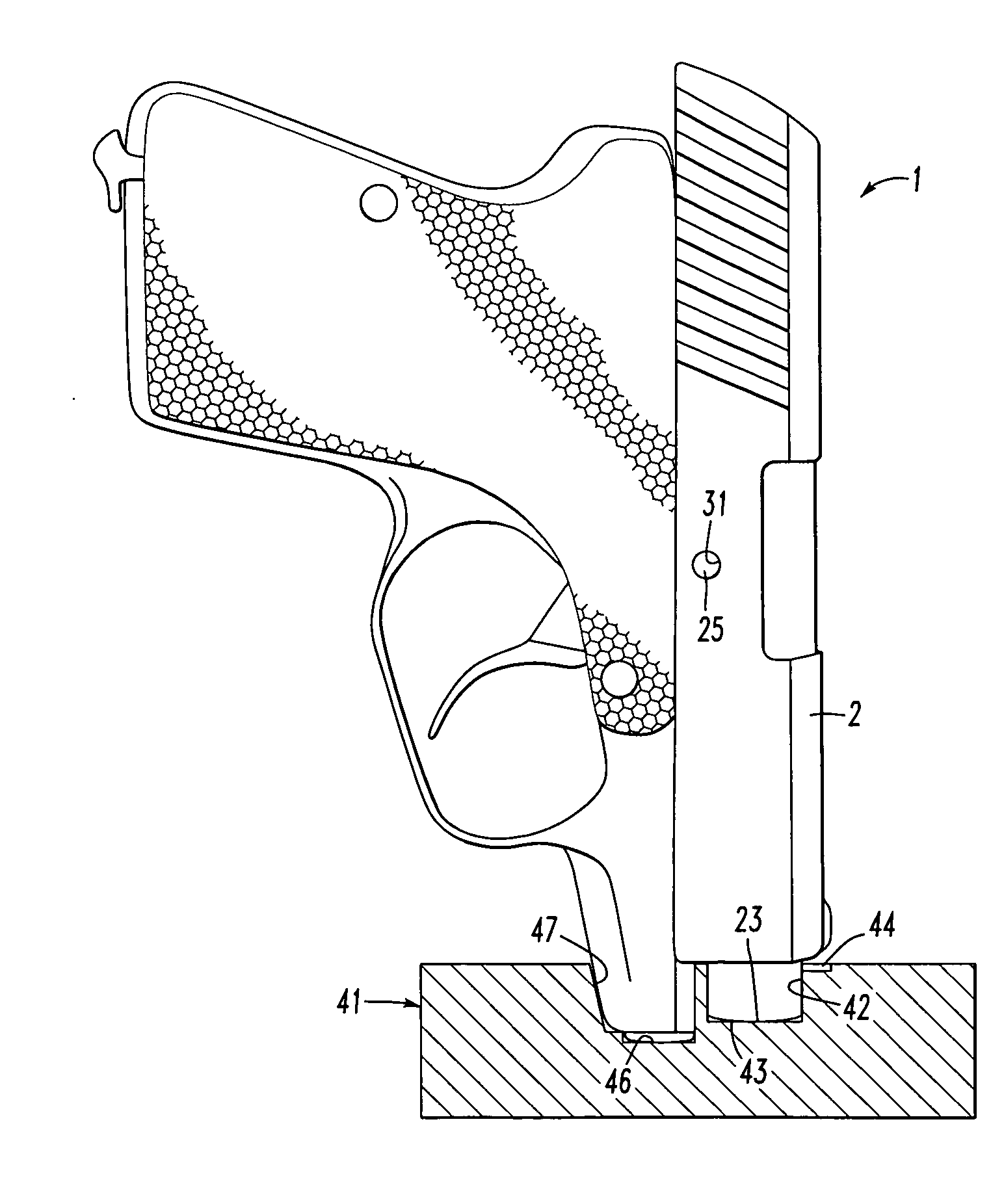
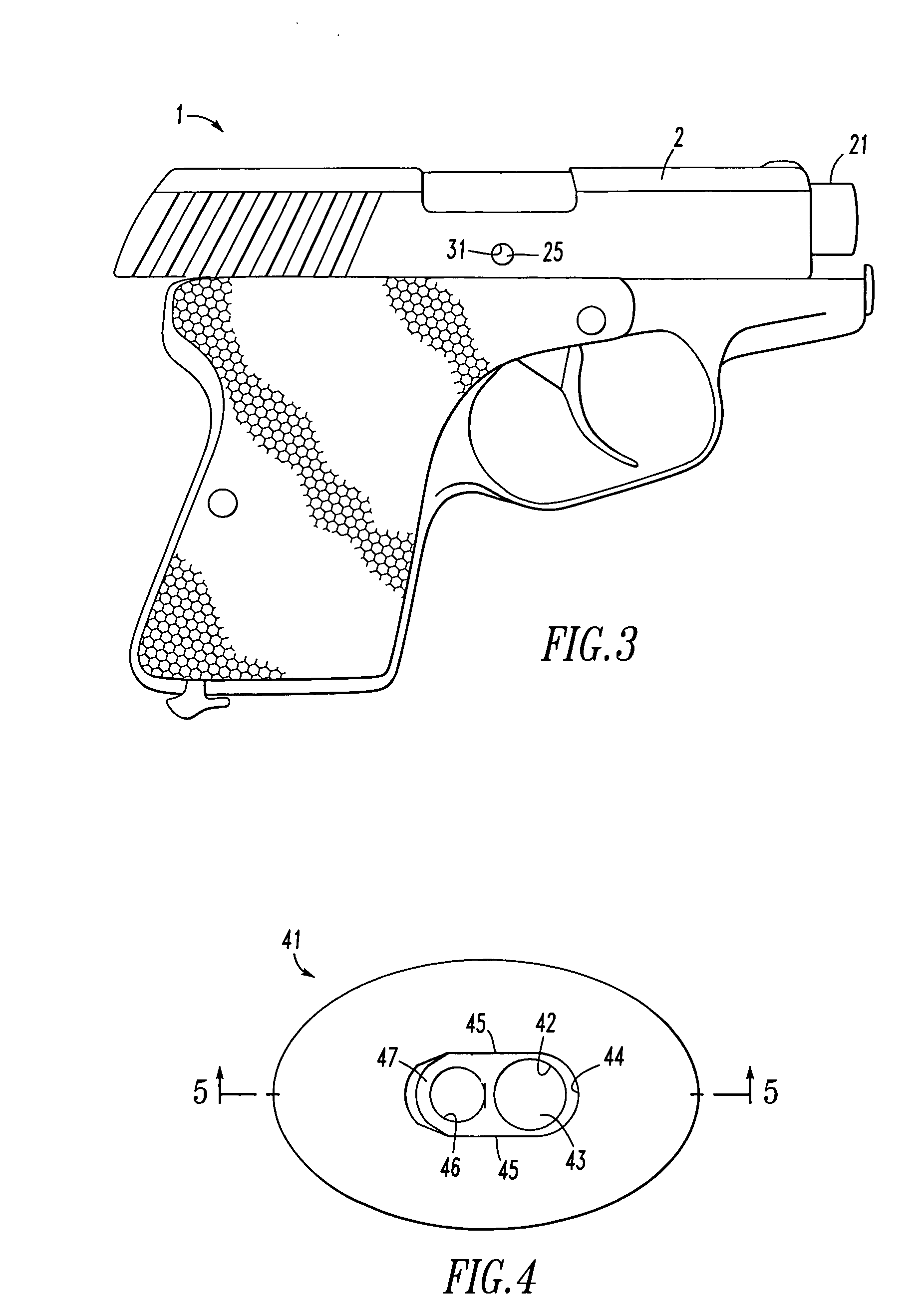
[0020] As shown in FIG. 2, rearward movement of the slide 2 exposes a barrel 21 and recoil assembly 22, and more particularly the barrel front face 23 and guide rod front face 24. FIG. 2 shows the slide 2 in a take-down position at which a barrel pin 25 is exposed through a drift hole 26 of the slide 2. The drift hole 26 is large enough for the barrel pin 25 to pass therethrough. FIG. 3 shows a reverse side of the handgun 1. The slide 2 includes an ejector side hole 31 that is smaller than the ba...


PUM


Abstract

The present invention relates to a device for placing a slide of a handgun in proper position relative to the barrel so that an otherwise concealed barrel pin is now revealed. The invention is particularly suited for handgun designs otherwise lacking a positive stop, external barrel pins or levers. The device includes an indentation for receiving a front face of the handgun. The indentation is at least partially surrounded by a raised ridge adapted to prevent the slide from entering the indentation. Placing the barrel in the indentation forces the slide backwards from the front face. The elevation difference between the depth of the indentation and the ridge is selected to expose a barrel pin of the handgun.

Description

[0001] The present application claims priority to U.S. 60 / 609,492, filed 13 Sep. 2004.FIELD OF THE INVENTION [0002] The present invention is directed to a device for disassembling and reassembling a handgun and, more particularly, to removal and installation of a barrel pin of a handgun. BACKGROUND [0003] The trend in firearm production, and in particular the production of handguns, has moved towards fewer moving parts. Benefits of fewer moving parts include improved reliability, reduced cost of manufacture, simplified assembly, disassembly and maintenance, and less chance of part failure. [0004] In addition to improved reliability and efficacy, the use of fewer moving parts can produce a light, compact firearm having improved ergonomics. Such firearms include handguns for self-defense purposes that are more easily concealable. For example, U.S. Pat. No. 6,070,512 to Rohrbaugh describes a handgun having a lightweight, compact, ergonomic construction. [0005] A handgun, such as one of...

Claims


Application Information

Patent Timeline
IPC IPC(8): F41C27/00
CPCF41C27/00F41A11/00
Inventor SHOBER, DAVID R.
Owner SHOBER DAVID R
Why Eureka
Try Eureka