Modular safety railing system

Inactive Publication Date: 2006-03-16
EISENKREIN LARRY
View PDF6 Cites 17 Cited by
  • Summary
  • Abstract
  • Description
  • Claims
  • Application Information

AI Technical Summary

Benefits of technology

[0012] Each of the structural components of the railing system are connected using temporary fastening methods such as screws or bolts, such that the rail can be easily erected at a desired site, and then broken down into component pieces when no longer needed. All of the components of the railing system are reusable avoiding the waste of material associated with the use of prior art handmade wooden railings.
[0013] The roof mounted post bracket is provided in a number of configurations, adapted to fit various style roofing systems. In each case the post bracket mounts at the edge of the roof and engages the top surface of the roof with a lower rail brace, along with a mount either underneath the overhang of the roof or extending downwards along the wall under a roof in cases where the roof edge is flush with the building wall. The lower brace provides increased stability for the post bracket at its base.
[0014] Each p

Problems solved by technology

Each year a significant number of workers are injured or killed by a fall.
Given that there are often numerous openings in buildings under construction that either would not be present, or would be protected with a finished railing in a completed building, it is not surprising that falling injuries are so prevalent in the construction industry.
The magnitude of this safety problem has drawn the attention of regulatory bodies such that in many jurisdictions, some form of barrier is now required around elevated work areas.
One problem with harnesses is that they can potentially limit the mobility of an individual worker.
In addition, where two or more people are working together, the potential to get safety lines tangled creates a potential nuisance as well as a hazard.
Further, harnesses do not prevent falls but only serve to limit the distance a person falls.
As a result it is

Method used


Image

  • Modular safety railing system
  • Modular safety railing system
  • Modular safety railing system

Examples


Example

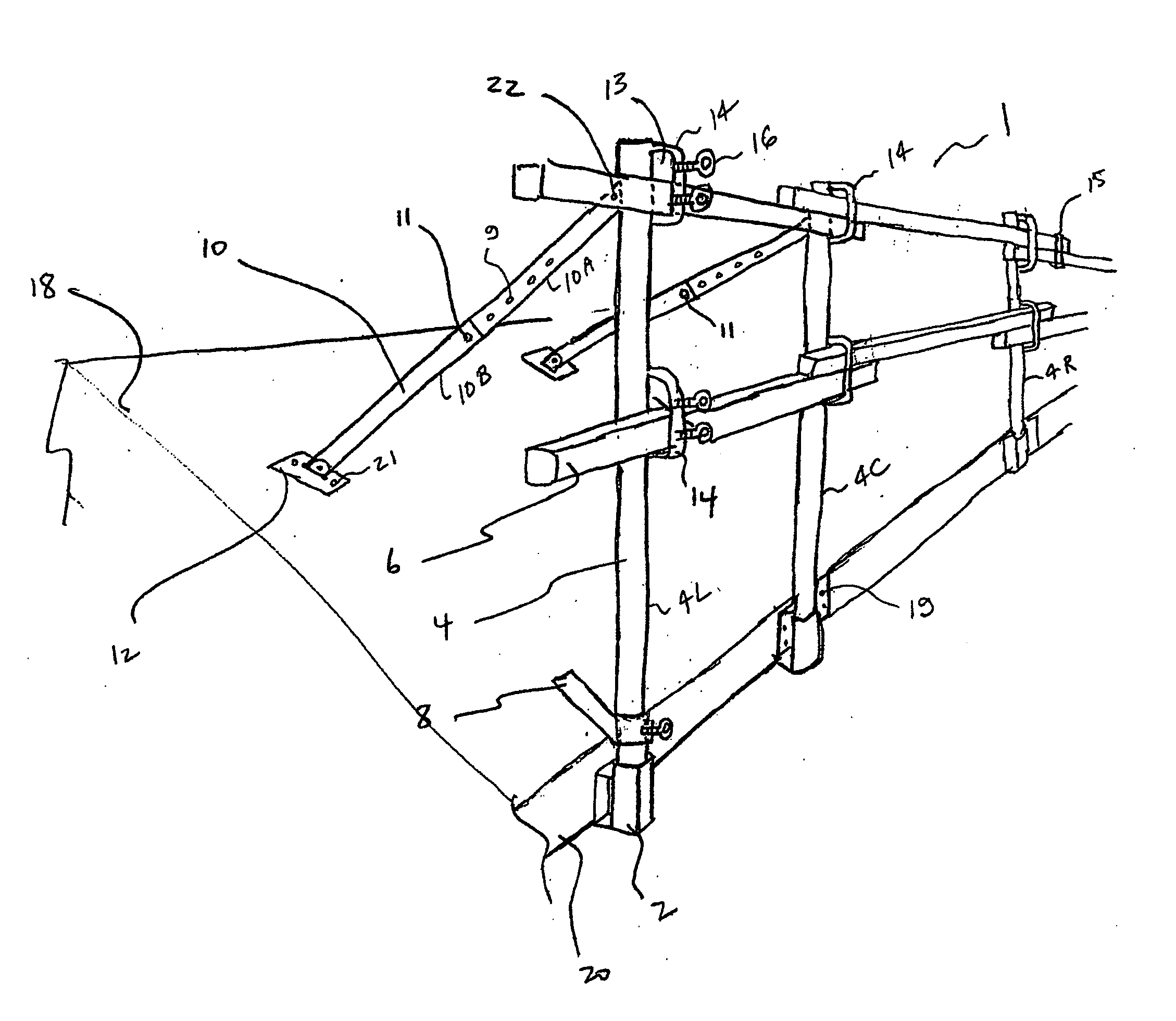
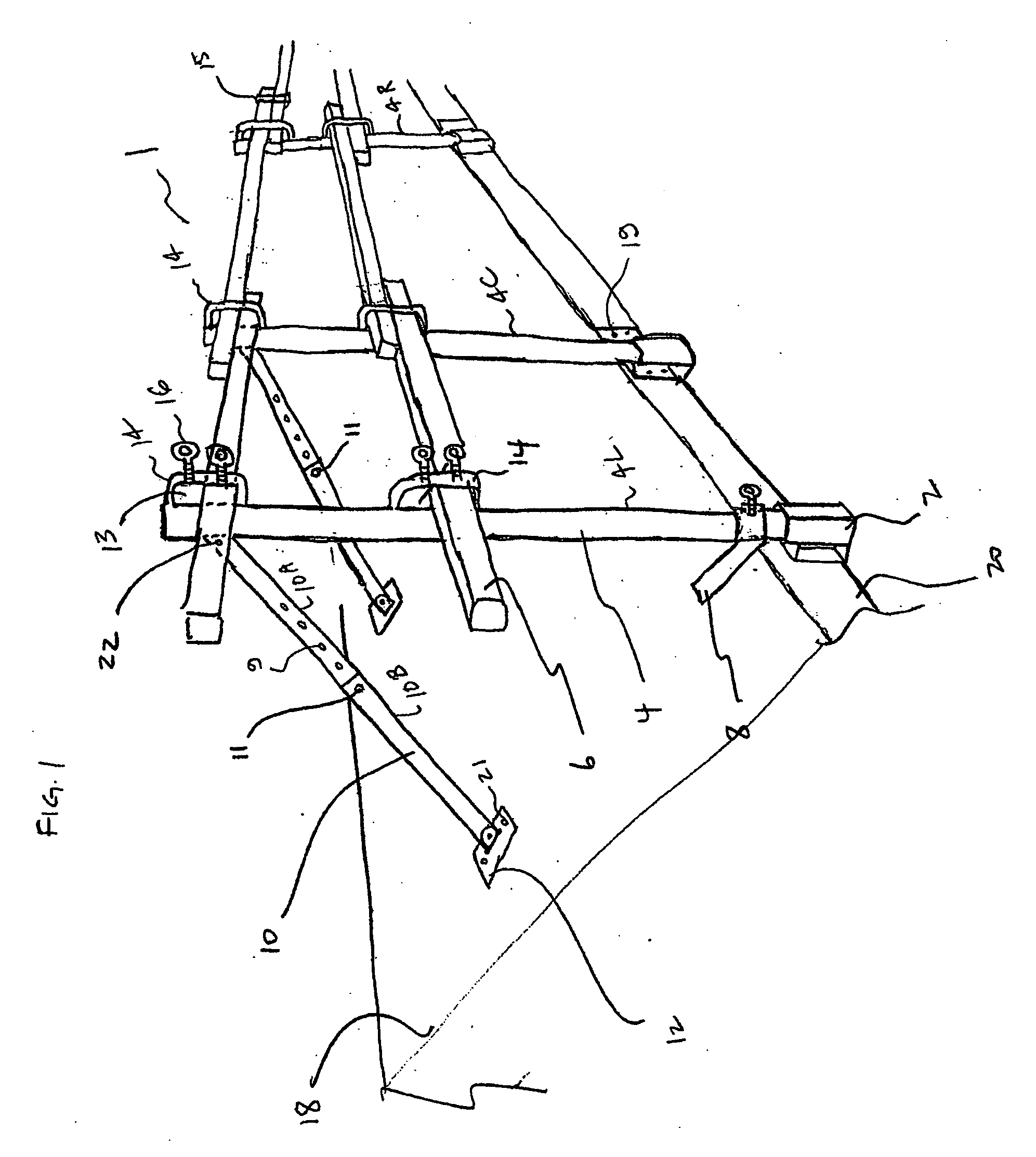
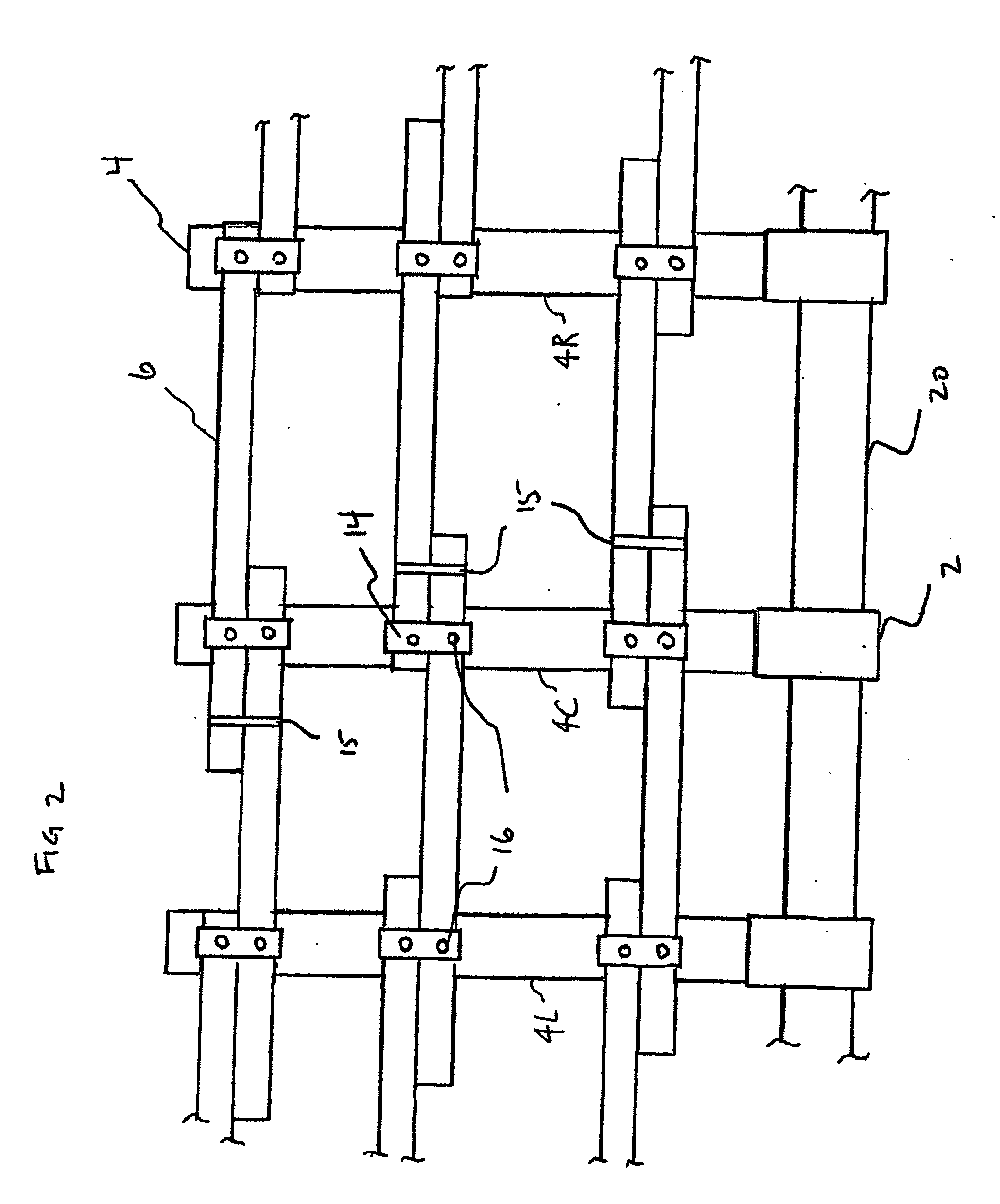
[0022] The invention provides a modular safety railing system comprising roof mounted post brackets, vertically oriented posts that insert into the post brackets and a series of lower and upper braces to further secure the bottom and top of the railing module to the roof. Each of the structural components of the railing system are affixed to the roof or each other using temporary fasteners such as screws or bolts. As such, the system can be easily erected at a desired site, and then broken down into component pieces to move to a new location. All of the components of the railing system of the invention are reusable, providing the advantage of a cost-effective apparatus for enhancing worker safety.

[0023] A safety railing is formed by placing railing modules along the edge of a roof or other area where a temporary safety railing is desired, and then placing horizontally oriented rails through the railing brackets of adjacent posts. The length of the railing is dictated by the number ...


PUM


Abstract

A modular safety railing system comprises post brackets adapted for attachment to a building structure. Posts are adapted to engage the post brackets the posts are oriented substantially vertically. Upper and lower rail mounts are located on each post and right and left upper and lower rails are releasably attachable at inner portions thereof to corresponding upper and lower rail mounts of a center post and are releasably attachable at outer portions thereof to upper and lower rail mounts of corresponding right and left posts. An upper brace is attached at an upper end thereof to the post and adapted at a lower end thereof for releasable attachment to the building structure. The upper brace is adjustable such that same can be attached to the building structure at an angle to the center post that is sufficient to support the center post in the substantially vertical orientation.

Description

[0001] This invention is in the field of safety equipment, and in particular safety railing systems for use at construction sites. BACKGROUND OF THE INVENTION [0002] Safety for workers is an ongoing concern among a number of industries and for the government agencies whose responsibility it is to enact and enforce regulations designed to improve workplace conditions. Each year a significant number of workers are injured or killed by a fall. [0003] Given that there are often numerous openings in buildings under construction that either would not be present, or would be protected with a finished railing in a completed building, it is not surprising that falling injuries are so prevalent in the construction industry. [0004] It is clearly an important consideration that workplaces are provided with adequate safety devices in order to reduce the risk of falls. The need for safety devices is even more critical when workers are placed at high levels, or when working on uneven or sloping su...

Claims


Application Information

Patent Timeline
IPC IPC(8): E04G3/32
CPCE04G21/3204E04G21/3233E04G21/3223E04G21/3214E04G5/041
Inventor EISENKREIN, LARRY
Owner EISENKREIN LARRY
Why Eureka
Try Eureka