Simplified sprayer device

Active Publication Date: 2006-03-16
MWV VICENZA SRL
View PDF14 Cites 15 Cited by
  • Summary
  • Abstract
  • Description
  • Claims
  • Application Information

AI Technical Summary

Benefits of technology

[0017] Another object of the present invention is to provide a sprayer device provid

Problems solved by technology

Sprayers according to the prior art present drawbacks.
Some drawbacks are due to the suction and delivery valve.
In fact said type of valve is quite delicate and therefore it is subject to frequent breakage, jamming and obstruction of the suction and delivery channels, with the result of making the sprayer unserviceable.
Other drawbacks are due to the spring which biases the trigger, which is generally disposed inside the body of the piston.
These characteristics ma

Method used


Image

  • Simplified sprayer device
  • Simplified sprayer device
  • Simplified sprayer device

Examples


Example

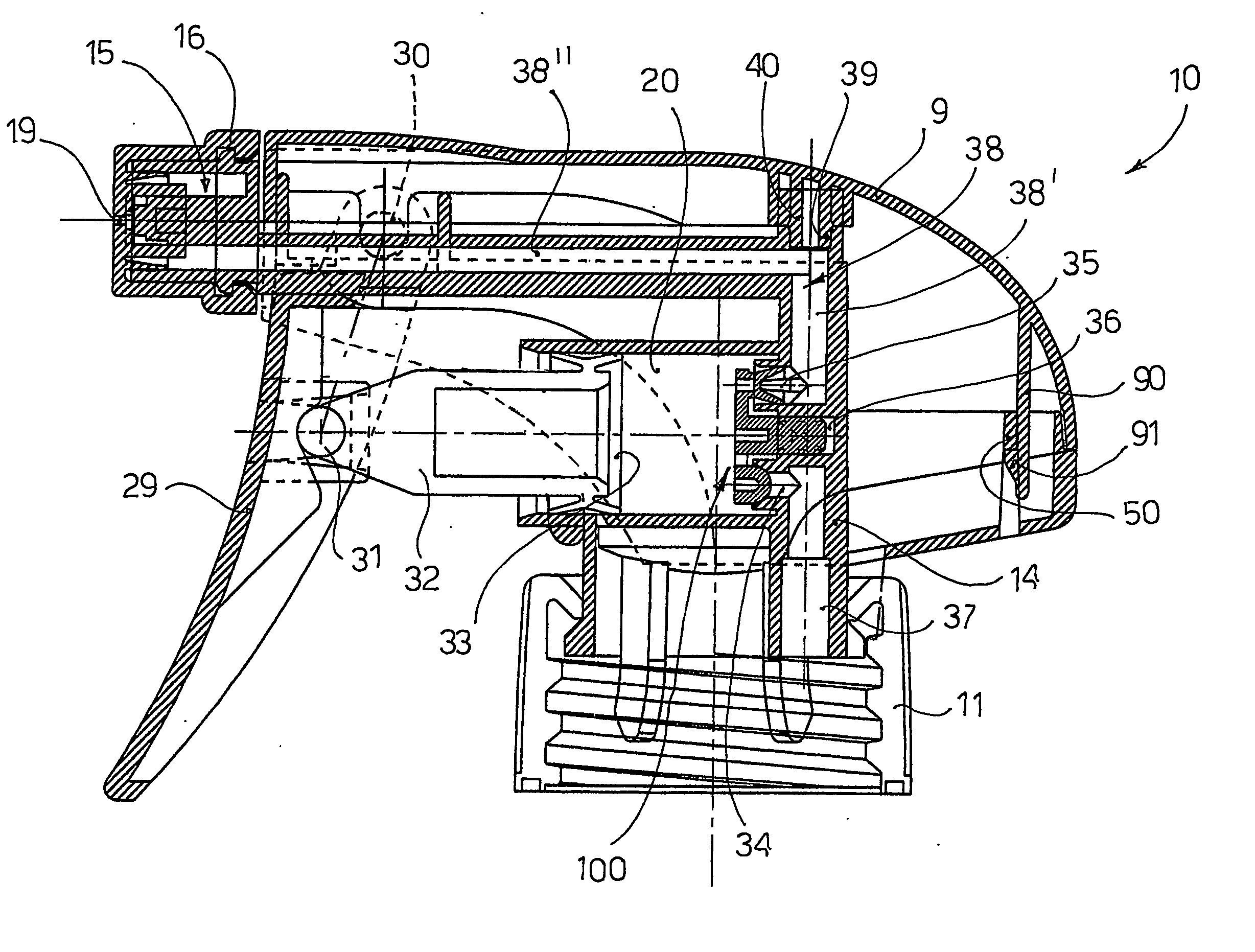
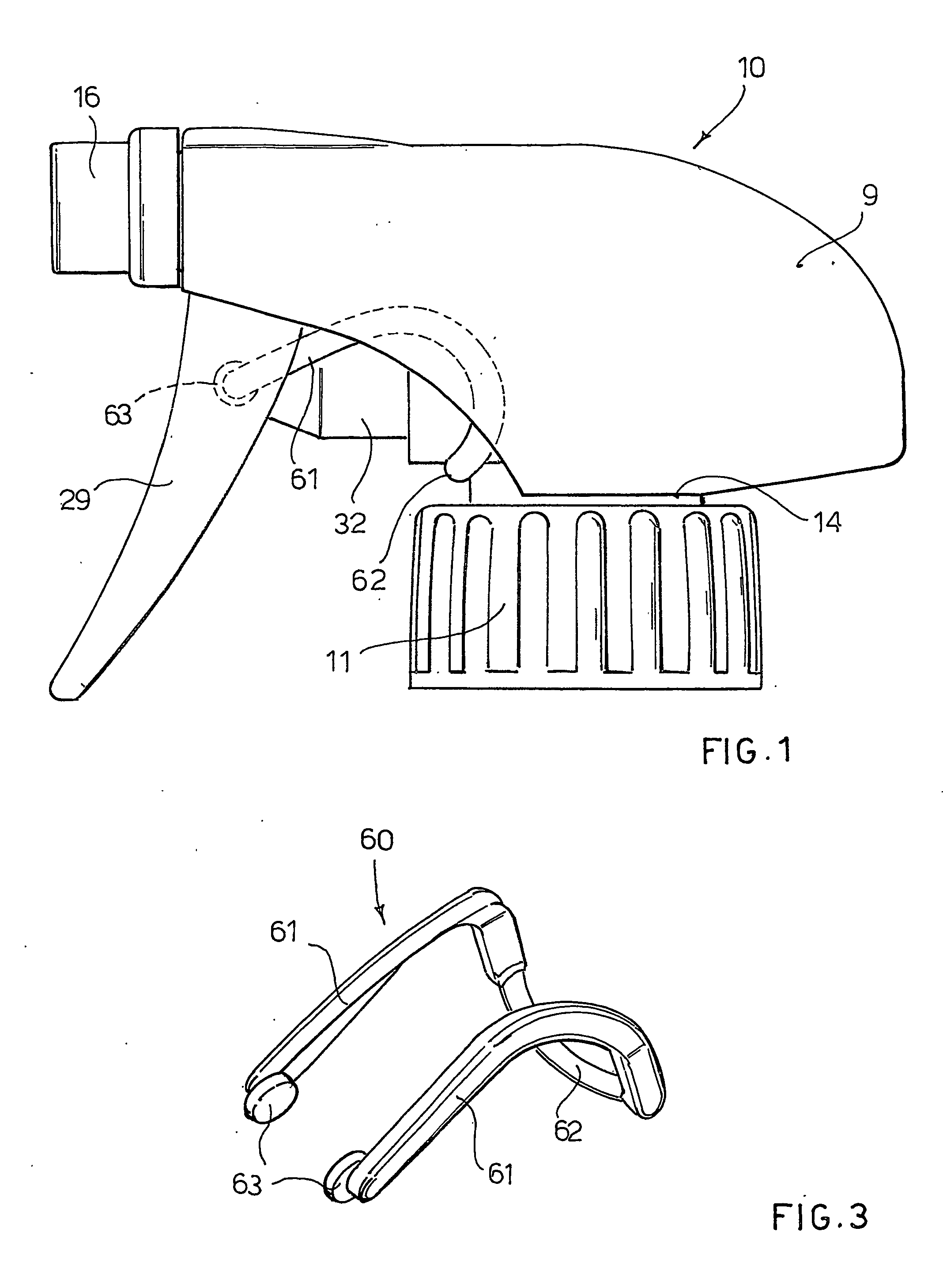
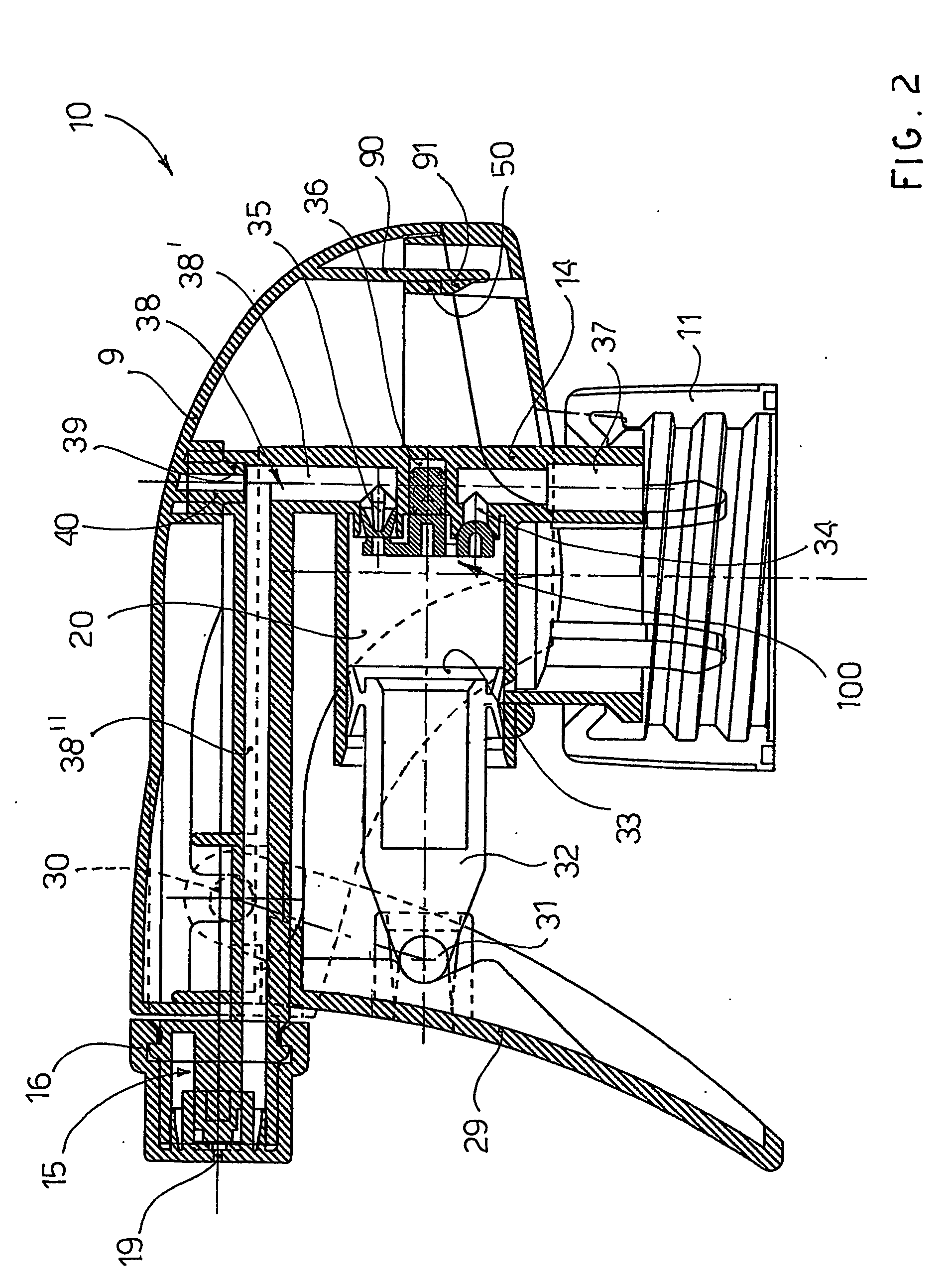
[0039] A sprayer device according to the invention, denoted as a whole with reference numeral 10, is described with the aid of the figures.

[0040] A fixing cap 11—having an inner thread suitable to engage with an outer thread of the mouth of a container (not shown) suitable for containing a liquid such as for example household cleaning liquids—is rotatably mounted at the base of the sprayer 10.

[0041] The cap 11 is mounted on a cylindrical base body connected to the sprayer body 14, which, as shown in FIG. 2, is substantially L-shaped and ends in a delivery nozzle 15 with an opening from which the liquid is delivered.

[0042] Above the front end of the body 14, wherein the sprayer nozzle 15 is positioned, a sprayer cap 16 is rotatably mounted. The sprayer cap 16 has at least one hole 19 for the passage of the liquid to be sprayed. When the sprayer cap 16 is positioned in the spraying position, delivery of liquid to the outside is allowed. On the other hand, when the sprayer cap 16 is...


PUM


Abstract

A sprayer device (10) with a trigger pump (29) includes a substantially L-shaped body (14) that can be applied to a container for liquids and is provided with a sprayer nozzle (15). A chamber (20) wherein a plunger (33) of the pump slides, an input duct (37) which puts the container into communication with the chamber and an output duct (38) which puts the chamber into communication with the nozzle are formed inside the body. A suction and delivery valve (100) which allows the suction of the liquid from the inside of the chamber and the delivery of the liquid from the chamber to the sprayer nozzle is installed in the chamber of the sprayer body. The stem (32) of the plunger of the pump is operated by a trigger (29) biased by a spring (60).

Description

CROSS-REFERENCE TO RELATED APPLICATION [0001] This application is a National Phase of International Application Serial No. PCT / EP04 / 000184, filed Jan. 14, 2004.BACKGROUND OF THE INVENTION [0002] 1. Field of the Invention [0003] The present invention refers to a sprayer device, such as a pump sprayer operated manually by means of a trigger lever. [0004] 2. Description of the Background Art [0005] Particular reference will be made hereinunder to sprayers for liquids, it being understood that said sprayers can also be used to spray any type of fluid, such as foams and the like, for example. [0006] A sprayer of this type generally comprises a main body provided with a base with a threaded cap to be applied to the mouth of a liquid container, a delivery nozzle from which the liquid is sprayed, a spring-biased trigger lever that can be operated manually by the user, and a pump operated by the trigger lever to suck the liquid from the container and to spray it through the sprayer nozzle. [...

Claims


Application Information

Patent Timeline
IPC IPC(8): A62C11/00B67D5/40B05B9/043B67D7/58B05B11/00
CPCB05B11/3011B05B11/3077B05B11/3074B05B11/3064B05B11/1011B05B11/1064B05B11/1077B05B11/1074
Inventor BUTI, SARIO
Owner MWV VICENZA SRL
Why Eureka
Try Eureka