System for securing a sign to a support surface

Active Publication Date: 2019-10-17
DANIA TECH APS
View PDF0 Cites 0 Cited by
  • Summary
  • Abstract
  • Description
  • Claims
  • Application Information

AI Technical Summary

Benefits of technology

The present invention is about a cheap and effective way to keep signs and name plates from being removed from their mounting base without permission.

Problems solved by technology

Unauthorized persons cannot remove the information-carrying part without having knowledge about the location of the magnetically releasable lock.

Method used


Image

  • System for securing a sign to a support surface
  • System for securing a sign to a support surface
  • System for securing a sign to a support surface

Examples


Embodiment Construction

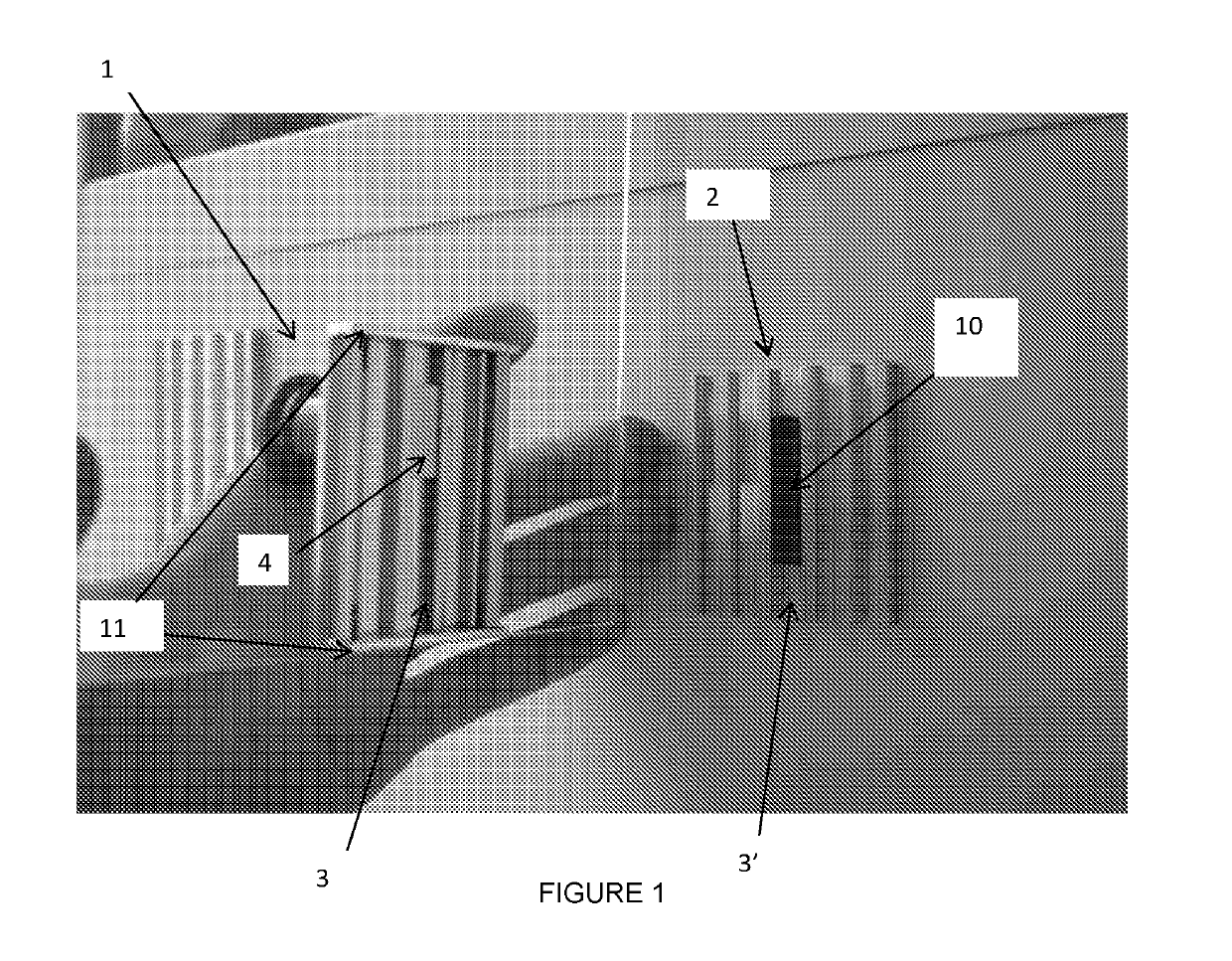
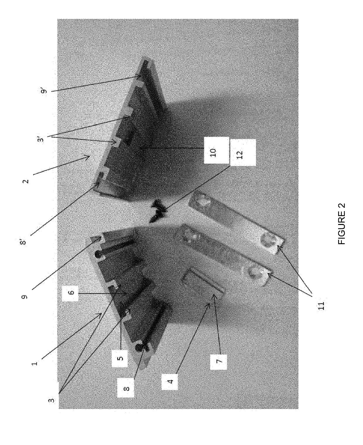
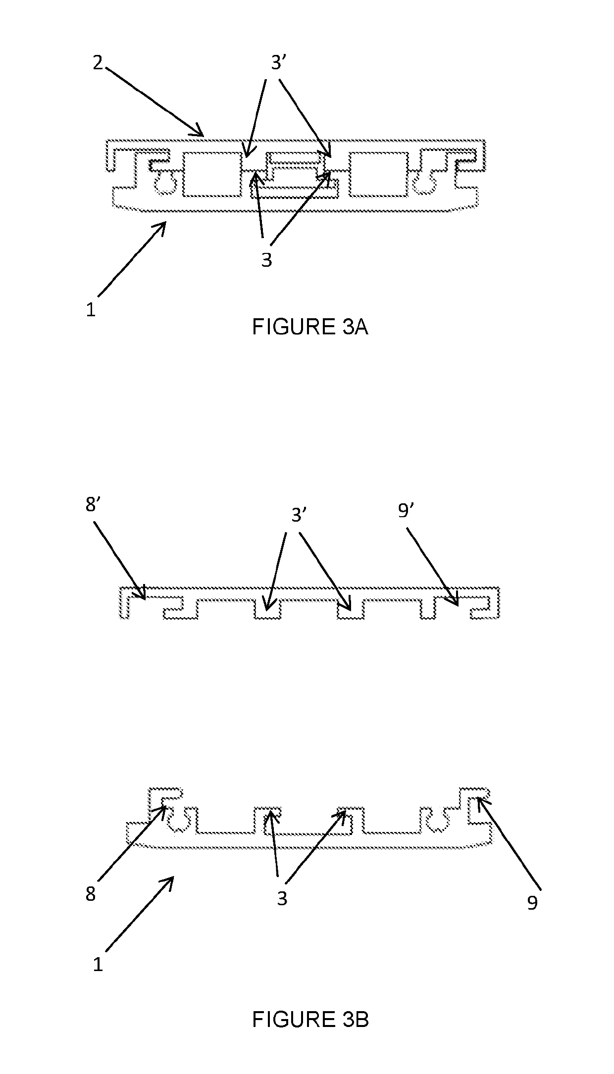
[0023]The system illustrated in FIGS. 1-2 comprises a sign-carrying part (1) for releasable attachment on a mounting part (2), said sign-carrying part (1) having a front side for holding the sign and a back side provided with a track (3) that loosely holds a locking plate (4), said track providing a compartment (5) for the locking plate (4) with an opening (6) distal to the back side of the sign-carrying part, said locking plate (4) provided with a protrusion (7) that protrudes beyond the opening (6) of the track (3) when the locking plate is resting on the inner surface of the track (3) distal to the back side. The mounting part (2) configured to be fixedly attached to a support surface, said mounting part (2) having a backside for mounting it on the support surface, and a front side with a track (3′) for receiving the protrusion (7) of the locking plate (4) thereby preventing lateral displacement / movement of the sign-carrying part (1).

[0024]As shown in FIGS. 1-3 the mounting part ...


PUM


Abstract

There is provided a system for securing a sign to a support surface. The system comprises a magnetically releasable lock adapted to automatically lock mutually displaceable surface portions together. The system ensures locking of the two mutually displaceable portions without the visible information-carrying part being disfigured. Unauthorized persons cannot remove the information-carrying part without having knowledge about the location of the magnetically releasable lock.

Description

FIELD OF THE INVENTION[0001]The present invention relates to a system for securing a sign to a support surface. More specifically the invention relates to a system comprising a magnetically releasable lock adapted to automatically lock mutually displaceable surface portions together.BACKGROUND OF THE INVENTION[0002]Signs, name plates and the like often need to be mounted on a base secured to a door or wall. These are prone to be subjected to unwarranted removal. This is particularly so with name plates which can readily be used by others. The unauthorized removal of name plates has led to considerable inconvenience and expense in providing replacements.[0003]Various sign devices of the above type are known. Such signs are used both as permanent signs and as signs, where the user according to his wishes can replace the information-carrying part with another information-carrying part. These sign devices are generally used without any locking of the information-carrying part in relatio...

Claims


Application Information

Patent Timeline
IPC IPC(8): G09F7/04G09F7/10G09F7/18
CPCG09F7/04G09F7/10G09F2007/1852G09F7/18G09F7/08
Inventor THODE, KEN
Owner DANIA TECH APS
Why Eureka
Try Eureka