Fault-tolerant magnetic bearing position sensing and control system

a technology of applied in the field of fault-tolerant magnetic bearing position sensing and control system, can solve the problems of inaccurate rotor position control, faulty position sensor, and inability to control bearing properties, such as magnetic field strength, during operation

Inactive Publication Date: 2006-03-16
HONEYWELL INT INC
View PDF14 Cites 36 Cited by
  • Summary
  • Abstract
  • Description
  • Claims
  • Application Information

AI Technical Summary

Benefits of technology

[0006] The present invention provides a fault-tolerant magnetic bearing position sensing and control system and method.
[0007] In one embodiment, and by way of example only, an active magnetic bearing sensing and control system for rotationally suspending a rotor that is configured to rotate about a rotational axis includes first and second primary displacement sensors, first and second secondary displacement sensors, and a controller. The first primary displacement sensor is configured to sense rotor displacements in a first axis that is perpendicular to the rotational axis and supply a displacement signal representative thereof. The second primary displacement sensor is configured to sense rotor displacements in a second axis that is perpendicular to the rotational axis and supply a displacement signal representative thereof. The first secondary displacement sensor is configured to sense rotor displacements in the first axis and supply a displacement signal representative thereof. The second secondary displacement sensor is configured to sense rotor displacements in the second axis and supply a displacement signal representative thereof. The controller is coupled to receive the displacement signals from each of the displacement sensors and a speed signal representative of a rotational speed of the rotor. The controller is operable, in response to receipt of the displacement signals and the speed signal, to determine operability of each of the displacement sensors.
[0008] In another exemplary embodiment, a method of determining the operability of a system that includes at least a rotor that is configured to rotate about a rotational axis, and one or more active magnetic bearings configured to rotationally suspend the rotor, includes the steps of sensing a first primary rotor displacement in a first axis that is perpendicular to the rotational axis, sensing a second primary rotor displacement in a second axis that is perpendicular to the rotational axis, sensing a first secondary rotor displacement in the first axis, sensing a second secondary rotor displacement in the second axis, and determining a rotational speed of the rotor. The validity of each of the sensed rotor displacements is determined based, at least in part, on the sensed rotor displacements and the determined rotational speed.
[0009] Other independent features and advantages of the preferred magnetic bearing sensing and control system will become apparent from the following detailed description, taken in conjunction with the accompanying drawings which illustrate, by way of example, the principles of the invention.

Problems solved by technology

Thus, the properties of the bearing, such as the magnetic field strength, may not be controlled during operation.
For example, if one or more of the position sensors is damaged, deteriorated, or otherwise experiences a fault, the faulty position sensor may supply inaccurate position information.
This in turn can lead to inaccurate rotor position controls and, in some instances, can result in the controller exciting fundamental vibrations in the rotor or in the inability of the controller to keep the rotor rotating within the mechanical limits of the magnetic bearing.

Method used


Image

  • Fault-tolerant magnetic bearing position sensing and control system
  • Fault-tolerant magnetic bearing position sensing and control system
  • Fault-tolerant magnetic bearing position sensing and control system

Examples


Embodiment Construction

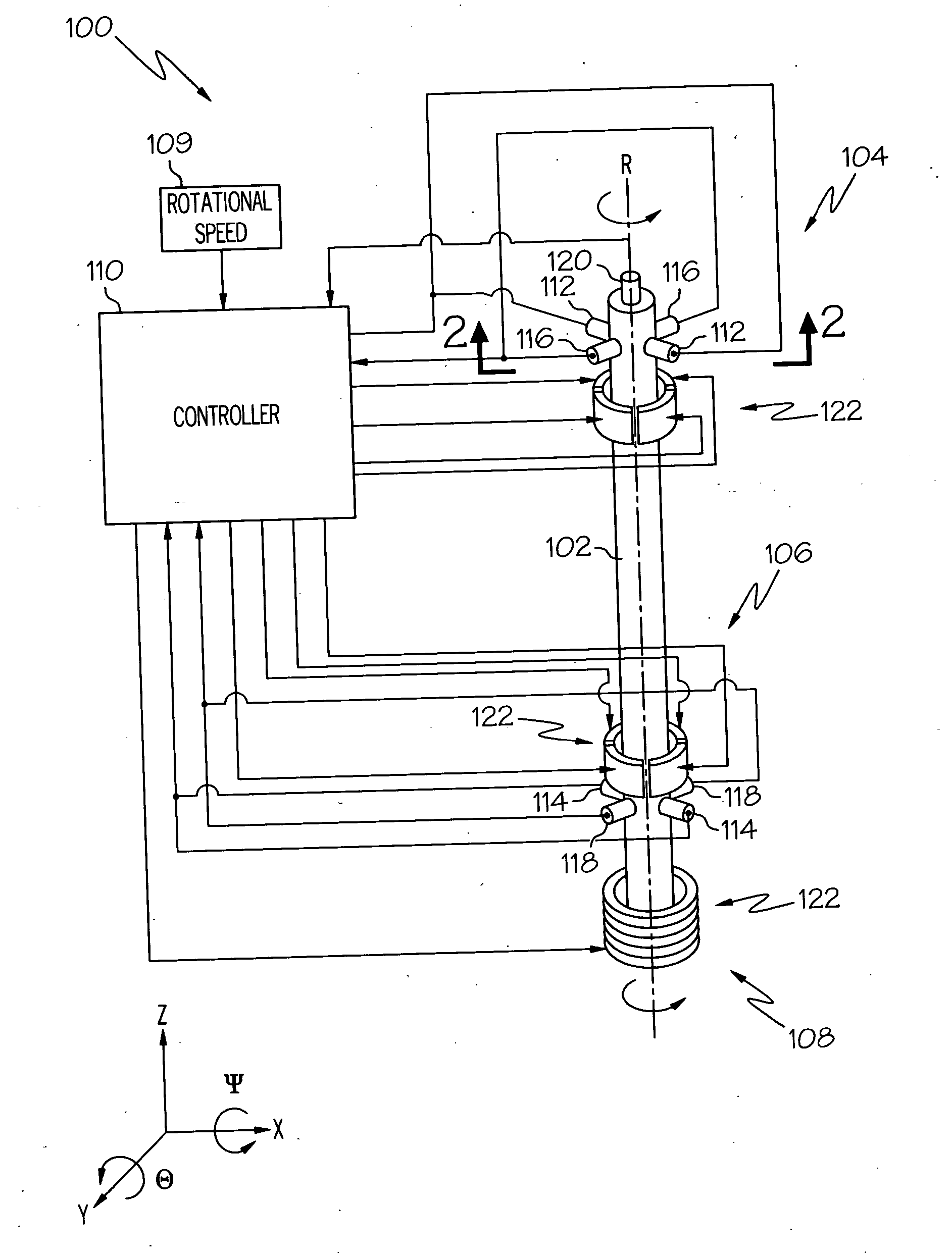
[0014] The following detailed description of the invention is merely exemplary in nature and is not intended to limit the invention or the application and uses of the invention. Furthermore, there is no intention to be bound by any theory presented in the preceding background of the invention or the following detailed description of the invention. In this regard, before proceeding with the detailed description, it is to be appreciated that the magnetic bearing system described herein is not limited to use with a particular configuration. Thus, although the magnetic bearing control system and method that is explicitly depicted and described is implemented using independent radial and axial bearing assemblies, it will be appreciated that other magnetic bearing configurations may also be used with the control system and method described herein. For example, the control system and method may also be used with a combination bearing configuration, or a conical bearing configuration.

[0015...


PUM


Abstract

A magnetic bearing sensing and control system and method provides increased tolerance to faults associated with the associated displacement sensors. The system includes a plurality of redundant displacement sensor sets to provide dual or triple displacement sensor redundancy, or higher if desired, and implements a process for determining when one or more displacement sensors is faulty. The system also compensates for determined sensor-related faults.

Description

TECHNICAL FIELD [0001] The present invention relates to magnetic bearings and, more particularly, to a fault-tolerant system and method for monitoring and controlling an active magnetic bearing system for use in various applications, including energy storage flywheels and other energy storage devices in both terrestrial and space applications. BACKGROUND [0002] Magnetic bearings have been used to suspend a rotational body, such as a rotor, in a non-contact fashion using magnetic force. That is, instead of physically supporting the rotor using lubricated bearings that physically contact the rotor, various magnets are spaced radially around the rotor and the magnetic forces supplied by the magnets suspend the rotor without any physical contact. In order to provide stable support for the rotor, the magnetic bearing suspends the rotor within five degrees-of-freedom. [0003] Generally, there are two categories of magnetic bearings, passive magnetic bearings and active magnetic bearings. P...

Claims


Application Information

Patent Timeline
Patent Type & Authority Applications(United States)
IPC IPC(8): H02K7/09
CPCF16C32/0442G05B9/03F16C32/0446
Inventor HANLON, CASEYPOTTER, CALVIN C.WINGETT, PAUL T.
Owner HONEYWELL INT INC
Why Eureka
Try Eureka