Chromatically enhanced display

a display and color technology, applied in the direction of measuring apparatus components, instruments, electrical apparatus, etc., can solve the problems of lack of drivers, lack of other gauges in the driver's console, and vehicle without power

Inactive Publication Date: 2006-03-16
AVAGO TECH ECBU IP (SINGAPORE) PTE LTD
View PDF6 Cites 12 Cited by
  • Summary
  • Abstract
  • Description
  • Claims
  • Application Information

AI Technical Summary

Benefits of technology

[0004] The present invention includes a display and method for displaying data. The display includes a light source and a gauge that displays a quantity. The gauge is illuminated by the light source that has a color specified by a first control signal. A controller generates the first control signal based on the quantity such that the light source generates light of a first color if the quantity is within a first range and light of a second color if the quantity is in a second range. In one embodiment, the light source is characterized by an intensity specified by a second control signal, and the controller generates the second control signal based on the quantity such that the light intensity has a first intensity value when the quantity is in a third range and a second intensity value when the quantity is in a fourth range. In one embodiment, the light intensity has a time varying pattern in the fourth range. In one embodiment, the controller includes a database for storing

Problems solved by technology

Unfortunately, the driver's attention is often focused on other tasks, and hence, the driver is not aware that the vehicle's speed is outside the limits allowed by the local laws until some other event calls the driver's attention to the vehicle's speed.
A similar problem exists for other gauges in the driver's console such as the fuel gauge.
Hence, if the engine overheats, the driver is not aware of the condition until some other event draws the driver's attention to

Method used


Image

  • Chromatically enhanced display
  • Chromatically enhanced display
  • Chromatically enhanced display

Examples


Embodiment Construction

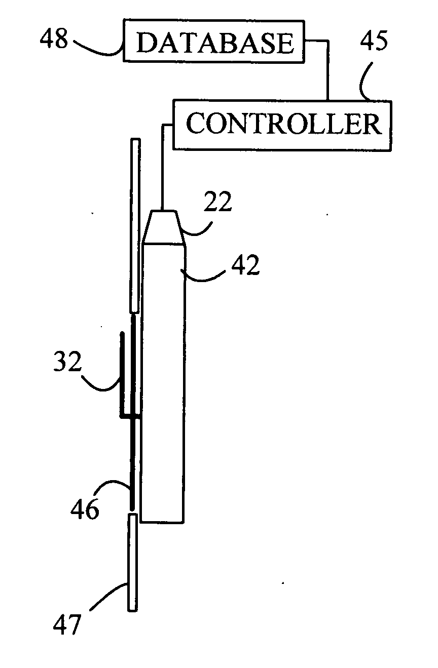
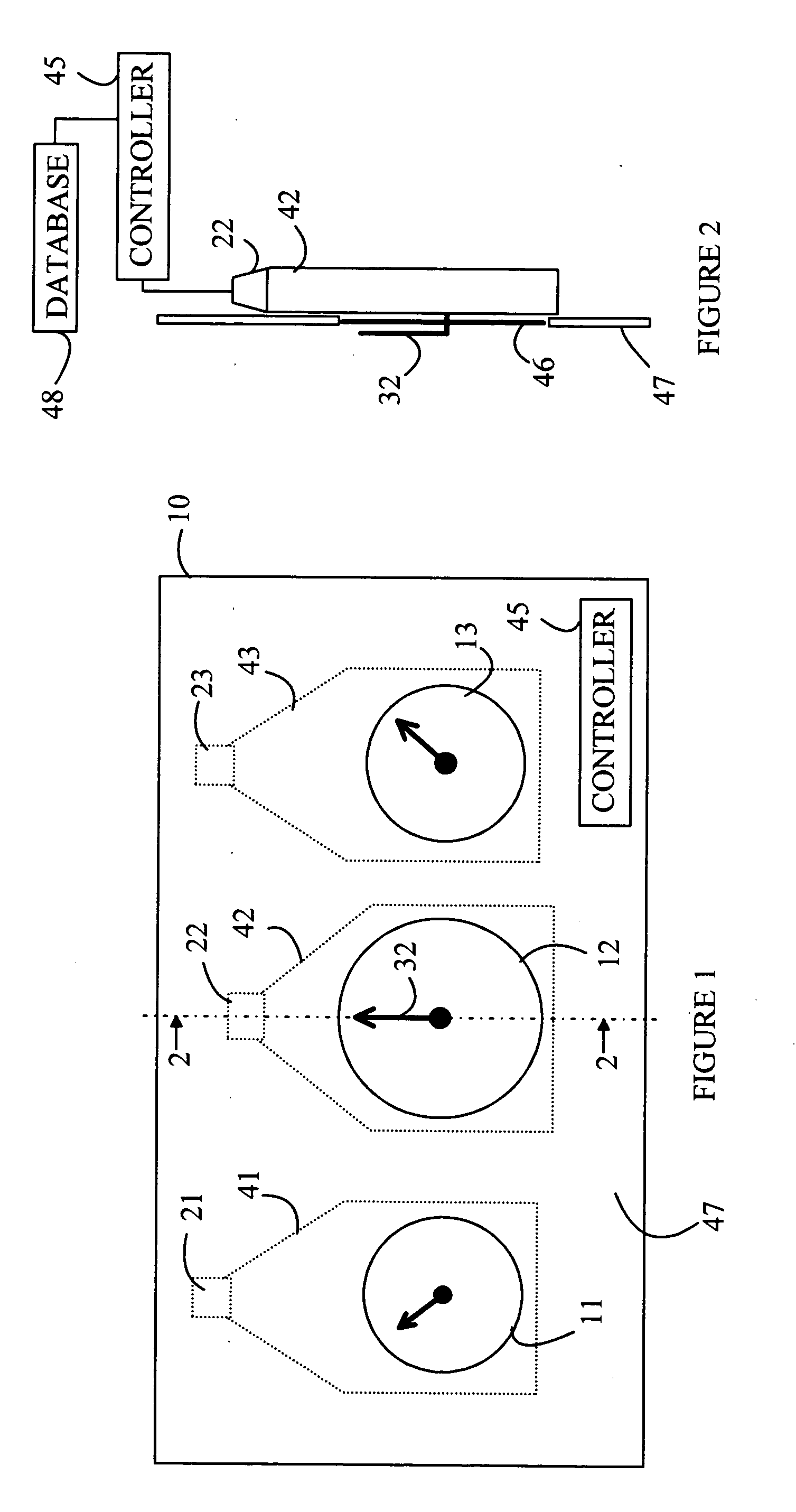
[0008] The present invention is based on the observation that the color of light emanating from a gauge on the display console can be perceived by the driver without requiring the driver to look directly at the gauge. Hence, if a display's color changes from one color to another, the driver can be alerted to a change in the condition of the quantity represented by the gauge in question. Thus alerted, the driver can look directly at the console and gauge in question to determine the cause of the change in condition signaled by the change in color. Since the gauges include a light source to illuminate the gauges, no additional light sources are needed, provided the light source has a color that can be changed.

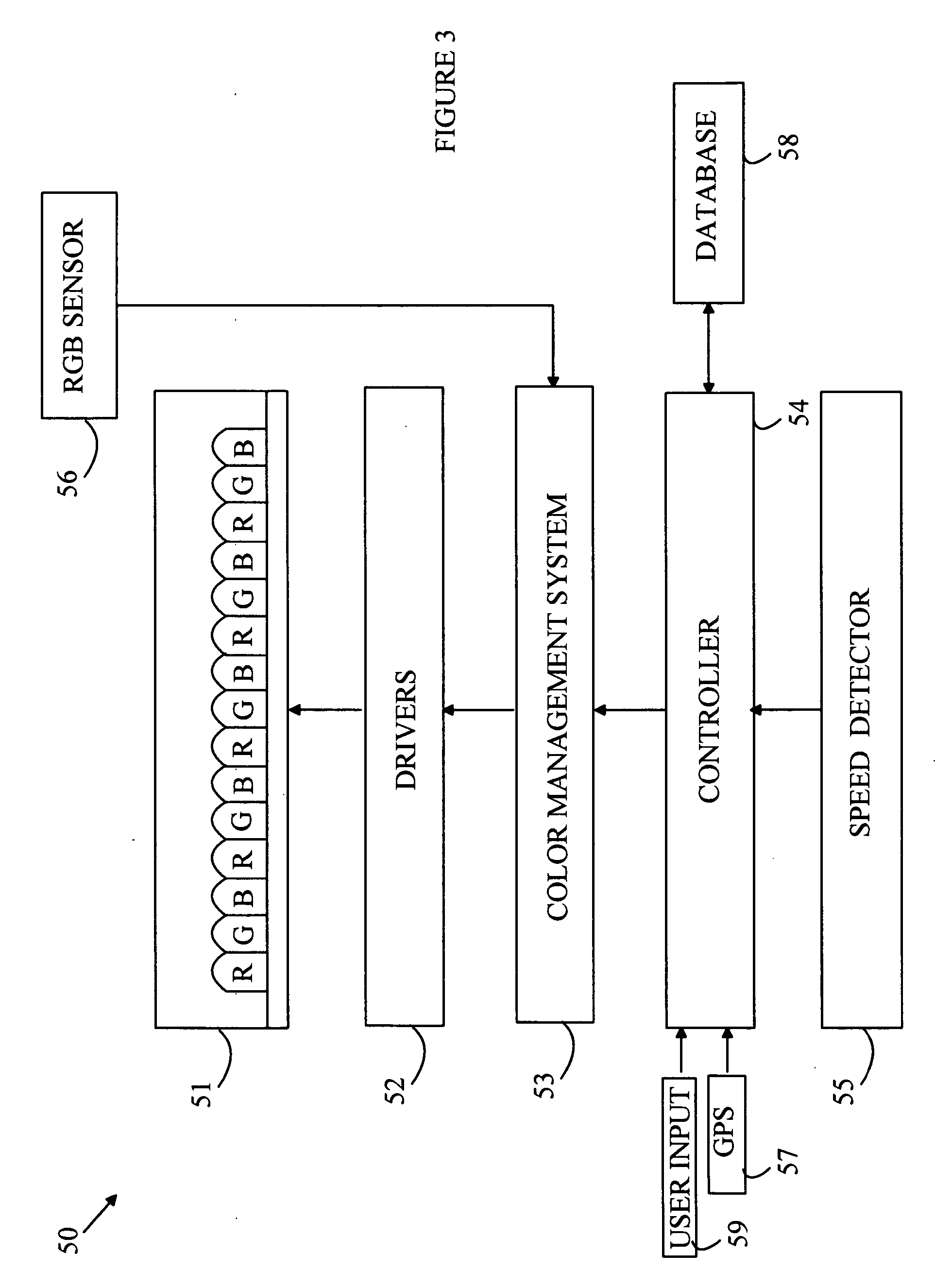
[0009] Light sources based on a plurality of LEDs are gaining favor for use in many applications because of the long lifetimes associated with such sources and the high efficiency of conversion of the electrical power to light. In such sources, the perceived color of the light i...


PUM


Abstract

A display and method for displaying data are disclosed. The display includes a light source and a gauge that displays a quantity. The gauge is illuminated by the light source that has a color specified by a first control signal. A controller generates the first control signal based on the quantity such that the light source generates light of a first color if the quantity is within a first range and light of a second color if the quantity is in a second range. In one embodiment, the light source is characterized by an intensity specified by a second control signal, and the controller generates a second control signal based on the quantity such that the light intensity has a first intensity value when the quantity is in a third range and a second intensity value when the quantity is in a fourth range.

Description

BACKGROUND OF THE INVENTION [0001] The present invention can be more easily understood with reference to a vehicle speedometer; however, it will become apparent from the following discussion that the present invention can be applied to a variety of displays. Most vehicles that are used on the public highways are equipped with a speedometer that displays the speed of the vehicle to the driver. The speedometer typically utilizes a pointer that rotates over a display having the various possible speeds thereon. Alternatively, the vehicle speed may be displayed as a digital readout. In either case, the vehicle design assumes that the driver periodically notes the driver's speed by looking directly at the speedometer and adjusts the speed to confirm to the limits associated with the roadway on which the vehicle is being operated. Unfortunately, the driver's attention is often focused on other tasks, and hence, the driver is not aware that the vehicle's speed is outside the limits allowed ...

Claims


Application Information

Patent Timeline
IPC IPC(8): G09G3/06
CPCG01D7/005G01D11/28H05B33/0872H05B33/0869H05B33/0863H05B45/20H05B45/22H05B45/28
Inventor CHEANG, TAK MENGNG, FOOK CHUINKO, CHOON GUANCHEW, CHOON KEAT
Owner AVAGO TECH ECBU IP (SINGAPORE) PTE LTD
Why Eureka
Try Eureka