Unlock instant, AI-driven research and patent intelligence for your innovation.

Illumination apparatus and projector display apparatus

a technology of projector display and illumination apparatus, which is applied in the direction of lighting and heating apparatus, instruments, television systems, etc., can solve the problems of difficult circuit scale reduction, high-voltage power source driving, and the miniaturization of the total illumination apparatus

Inactive Publication Date: 2006-03-16
OLYMPUS CORP
View PDF9 Cites 7 Cited by
  • Summary
  • Abstract
  • Description
  • Claims
  • Application Information

AI Technical Summary

Benefits of technology

This solution enables the production of intense, focused light with improved light use efficiency, reducing power consumption and allowing for the miniaturization of illumination systems while maintaining high brightness and condenser efficiency.

Problems solved by technology

Additionally, even with the light emitting source of the small-sized discharge type, the driving by a high-voltage power source is required in which it is difficult to reduce a circuit scale.
There are other many problems with respect to the miniaturization of the total illumination apparatus.
It is said that the miniaturization has already substantially approached limitation.
Therefore, the colors other than the separated color are uselessly discarded by the filter in many cases.

Method used


Image

  • Illumination apparatus and projector display apparatus
  • Illumination apparatus and projector display apparatus
  • Illumination apparatus and projector display apparatus

Examples


first embodiment

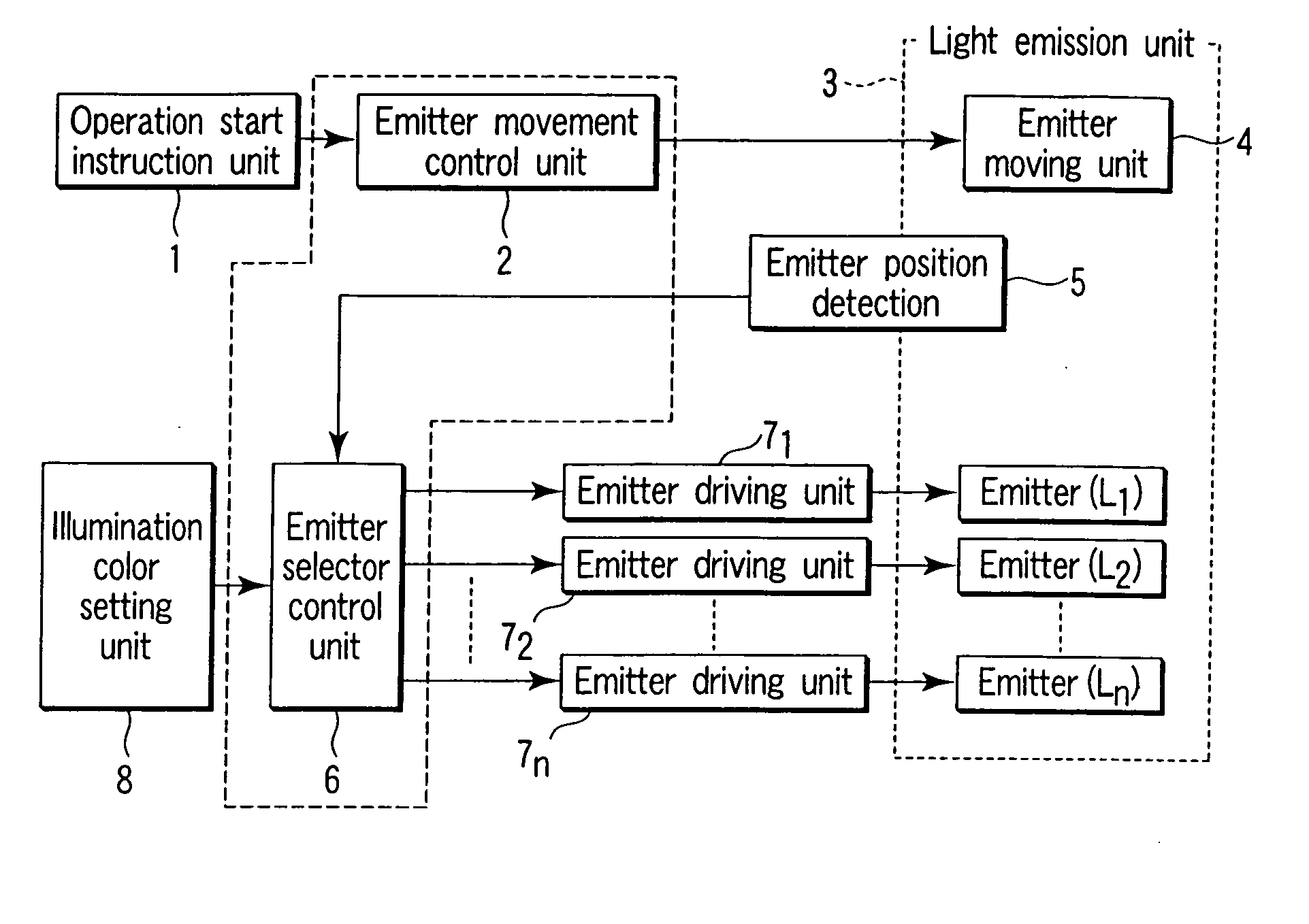
[0053] First, the basic illumination principle of an illumination apparatus according to a first embodiment will be described with reference to FIGS. 1 through 6B.

[0054] Here, a description is given of the illumination principle with reference to FIGS. 1 and 2. The “Illumination principle” means to illuminate brightly an illuminated area by emitter driving units 71-7n (collectively referred to as emitter driving units 7) as lighting units, optical lenses 17 and 18 as an optical system, an emitter moving unit 4 as a movement unit, an emitter movement control unit 2 and an emitter selector control unit 6 which act as a light selector control unit. The emitter driving units 7 have a function for adjusting the intensities of light emitted by emitters, for example, high-brightness light emitting diodes (hereinafter referred to as LED chips).

[0055] The optical lenses 17 and 18 cause light emitted from an emitter to converge onto the illuminated area. The emitter moving unit 4 allows a s...

second embodiment

[0077] Next, a second embodiment of the present invention will be described. The second embodiment is directed to an illumination apparatus required to illuminate brightly and uniformly an illuminated area so that there is a large difference in brightness between the illuminated area and a non-illuminated area like a spotlight or the illumination system of a projector display apparatus utilizing the aforementioned basic principle. To simplify the description, like the first embodiment, the second embodiment will also be described in terms of an illumination apparatus adapted for short-time illumination.

[0078] First, an illumination apparatus which brightly illuminates an illuminated area with concentrated light or collimated light like a spotlight and does not illuminate areas other than the illuminated area will be described with reference to FIGS. 7 through 21.

[0079] Here, the spotlight requires an optical system that illuminates brightly and uniformly a restricted illuminated a...

third embodiment

[0122] A third embodiment of the present invention will be described next. The third embodiment is an application of the lighting control of the illumination apparatus based on the basic illumination principle according to the second embodiment to a projector display apparatus.

[0123] The projector display apparatus needs an illumination apparatus adapted to brightly illuminate the illuminated area 34 with concentrated or collimated light and not to illuminate other areas than the illuminated area.

[0124] To obtain good projected images, the projector display apparatus of the present embodiment includes a light selector control unit which provides timing control of the moving unit and the lighting unit, lighting control of LED chips for providing color projected images, and control of a light modulation device for switching light modulated states according to color image data R, G and B, which will be described below.

[0125] When liquid crystals are used as the light modulation devi...


PUM


Abstract

An illumination apparatus which directs light from a light source to an illuminated area. The illumination apparatus comprises a plurality of light emitters as the light source, a lighting unit configured to cause the light emitters to emit light so that the intensities of light emitted by the light emitters can be adjusted, an optical system configured to direct light emitted by the light emitters to the illuminated area, a storing unit (e.g., ROM 61b) configured to store an adjusting amount of the emitted light for changing the intensities of light emitted together with time, and a lighting control unit configured to control the lighting unit based on the adjusting amount of the emitted light stored in the storing unit so that the respective light emitters carry out pulsed emission at different timings. The adjusting amount of the emitted light stored in the storing unit is an adjusting amount so as to change the intensities of light in a pulsed emission period of the respective light emitters.

Description

CROSS-REFERENCE TO RELATED APPLICATIONS [0001] This application is a continuation of U.S. patent application Ser. No. 10 / 635,192, filed Aug. 6, 2003, which claims the benefit of priority from the prior Japanese Patent Application No. 2002-230207, filed Aug. 7, 2002, the entire contents of which are incorporated herein by reference.FIELD OF THE INVENTION [0002] This invention relates to an illumination apparatus which has the high condenser capability and the high brightness and is possible to miniaturize the whole illumination apparatus, and to projector display apparatus using such an illumination apparatus. BACKGROUND [0003] Examples of a condenser illumination apparatus which illuminates a specified portion with high efficiency have heretofore been known such as a car headlight, stand illumination, spot light, flashlight, and illumination unit for a data projector. In this condenser illumination apparatus, light from a light emitting source closer to a point source is reflected b...

Claims


Application Information

Patent Timeline
Patent Type & Authority Applications(United States)
IPC IPC(8): G03B21/26F21S2/00G03B21/14F21V5/04F21V14/00F21Y101/02H01L33/58H01L33/60H04N9/31
CPCH04N9/3197H04N9/315
Inventor MATSUI, SHINZO
Owner OLYMPUS CORP