Fresnel lens and lighting apparatus provided with the fresnel lens

a technology of fresnel and lens, which is applied in the direction of lighting apparatus, lighting applications, instruments, etc., can solve the problems of inability to achieve sufficient stage effects, and inability to restrain unevenness in illuminating intensity, so as to reduce uneven brightness of illuminating beams and high stage effects

Inactive Publication Date: 2006-03-16
KK TOSHIBA
View PDF7 Cites 20 Cited by
  • Summary
  • Abstract
  • Description
  • Claims
  • Application Information

AI Technical Summary

Benefits of technology

[0014] Accordingly, an object of the present invention is to provide a lighting apparatus that attains high stage effects to reduce uneven brightness in illuminating beam, and a Fresnel lens that realizes such a lighting apparatus.

Problems solved by technology

Generally, a convex lens is formed into a relatively thick body having a spherical surface or an elliptic surface to provide a sufficient lens power, and the weight thereof becomes heavy.
However, in lighting apparatus using conventional Fresnel lens, unevenness in illuminating intensity cannot be restrained, and sufficient stage effects cannot be attained.
The rise surfaces cause light rays that are reflected or refracted to the outside of radiation area, and the rise surfaces partially block the illuminating beam, and dark lines that are darker than the circumferences thereof occur in the illuminating beam, causing unevenness in brightness.
Although designs to reduce uneven brightness in illuminating beam have been made in the conventional Fresnel lenses, it is pointed out that the conventional designs fail to reduce unevenness sufficiently.
Further, even if a Fresnel lens is so designed as to have segment lenses which provide no overlapping between the illumination distribution components, the lens surfaces of the segment lenses may be slightly displaced owing to a production error or the like, as a result, overlapping of the illumination distribution components occurs, leading to illumination unevenness.
As described above, in lighting apparatuses using the conventional Fresnel lens, there has not been proposed any effective method to solve the uneven illumination, accordingly, the improved Fresnel lens is expected.

Method used


Image

  • Fresnel lens and lighting apparatus provided with the fresnel lens
  • Fresnel lens and lighting apparatus provided with the fresnel lens
  • Fresnel lens and lighting apparatus provided with the fresnel lens

Examples


Embodiment Construction

[0053] A Fresnel lens according to embodiments of the present invention and a lighting apparatus therewith are illustrated in more details by reference to the attached drawings hereinafter. In the description which follows, in principle the same numeral is allotted to the same component, and repeated explanations thereof are omitted.

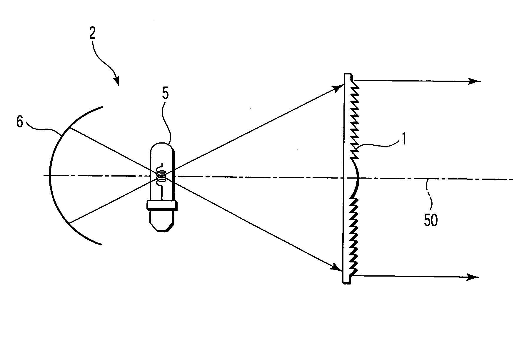
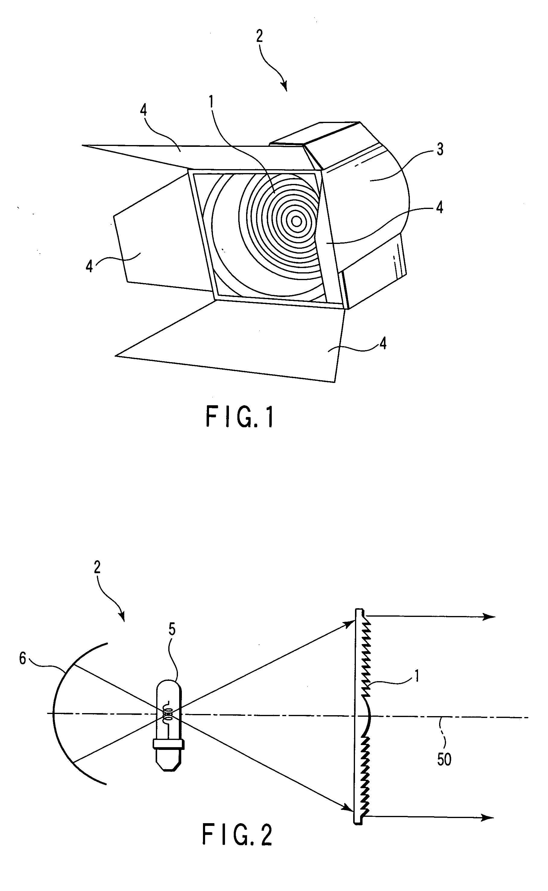
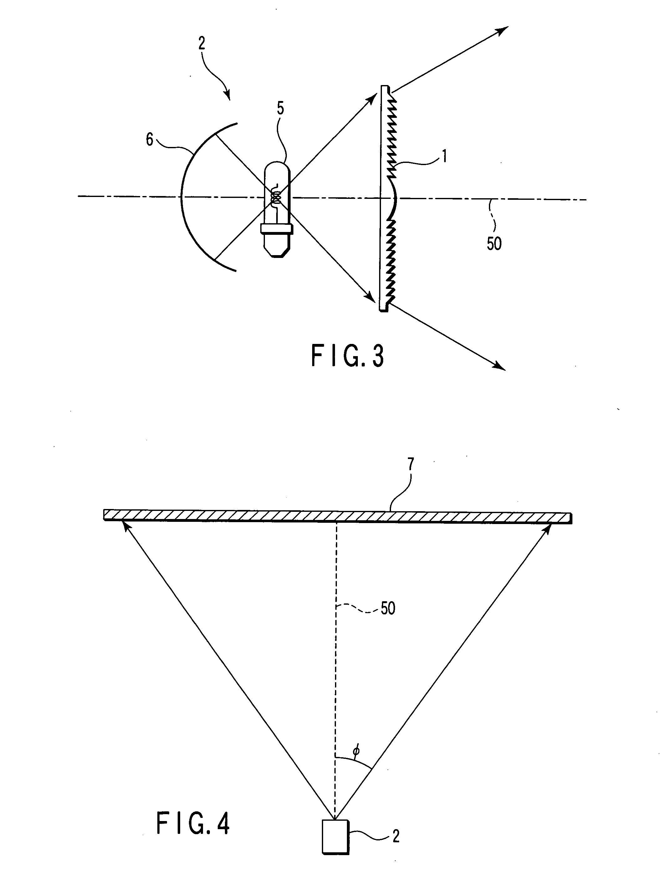
[0054]FIG. 1 is a perspective view schematically showing a lighting apparatus provided with a Fresnel lens according to one embodiment of the present invention. As shown in FIG. 1, a lighting apparatus 2 has a housing 3 and a Fresnel lens 1 arranged at the opening of the housing 3, and a light source 5 is arranged on the optical axis of the Fresnel lens 1 in the housing 3, as shown in FIGS. 2 and 3. Further, a convex mirror 6 is arranged as a light reflecting unit at rear side of the light source 5 in the housing 3 to reflect the beam from the light source 5 to the Fresnel lens 1. Further, a light controller, i.e., a louver 4 is provided at the front si...


PUM


Abstract

In a Fresnel lens which is made of a lens material whose refraction index is n, and focuses light beam from a light source at a specified radiation view angle φ, and has plural N pieces of circular lens surfaces arranged concentrically around a common optical axis, and plural circular rise surfaces arranged adjacent alternately between these lens surfaces, and two lens surfaces adjacent via at least one of the rise surfaces are concave surfaces, and tangent lines and at the intersecting point with the rise surfaces of the shape of a cross section passing through the optical axis of those lens surfaces intersect at the outside with respect to the optical axis, and when the angle formed between these tangent lines is defined as θ, a relational equation θ≧φ/(2 n N) stands.

Description

CROSS-REFERENCE TO RELATED APPLICATIONS [0001] This application is based upon and claims the benefit of priority from prior Japanese Patent Application No. 2004-269226, filed Sep. 16, 2004, the entire contents of which are incorporated herein by reference. BACKGROUND OF THE INVENTION [0002] 1. Field of the Invention [0003] The present invention relates to a Fresnel lens and a lighting apparatus provided with the Fresnel lens, and more specifically to a lighting apparatus using a Fresnel lens for an illumination spotlight used on stages and studios and a Fresnel lens used therein. [0004] 2. Description of the Related Art [0005] A lighting apparatus is used in the stage lighting and the studio lighting, which is generally suspended from the ceiling. In a possibility of its fall, it is desired that lighting apparatus is light in weight from the viewpoint of safety. Generally, lighting apparatus is provided with a light source of high brightness. Thus, the lighting apparatus is heated t...

Claims


Application Information

Patent Timeline
Patent Type & Authority Applications(United States)
IPC IPC(8): F21V5/00F21Y101/00
CPCF21V5/045G02B3/08F21W2131/406
Inventor MORINO, TAKESHIHONGUH, YOSHINORISHIRATSUCHI, MASATAKATOKUHARA, NAOTO
Owner KK TOSHIBA
Why Eureka
Try Eureka