Credit transmission rate control for a wireless communication system

a wireless communication system and transmission rate technology, applied in the field of communication systems, can solve the problems of insufficient customers within a particular area, customers located too far from the dslam, and limited dsl service speed,

Inactive Publication Date: 2006-03-16
SPRINT CORPORATION
View PDF18 Cites 78 Cited by
  • Summary
  • Abstract
  • Description
  • Claims
  • Application Information

AI Technical Summary

Benefits of technology

[0028] In some examples of the invention, the wireless communication system increases the first credit transmission rate and the second credit transmission rate in response to the collisions on the shared wireless link.

Problems solved by technology

Unfortunately, the speed of DSL service is limited by the distance between the customer and the DSLAM.
Customers located too far from the DSLAM may not be able to receive high-speed service.
Also, there may not be enough customers within a particular area to make it economical to install a DSLAM.
The quality of DSL service is also limited by the quality of the copper wire that connects the customer to the DSLAM.
Furthermore, DSL service does not work over Digital Loop Carrier (DLC) lines.
Unfortunately, the cable modem uses up valuable bandwidth on the phone line in the one-way system.
One problem is the delay from transmitting a credit from the upstream manager to the wireless broadband router to the time the packet is transmitted from the wireless broadband router to the upstream manager.
Another problem is the 25 ms delay reduces the utilization in many scenarios.
Another problem is how to control traffic on the upstream bandwidth to maximize upstream utilization.

Method used


Image

  • Credit transmission rate control for a wireless communication system
  • Credit transmission rate control for a wireless communication system
  • Credit transmission rate control for a wireless communication system

Examples


Embodiment Construction

Broadband Wireless System—FIGS. 1-6

[0051]FIGS. 1-6 depict a specific example of a broadband wireless system in accord with the present inventions. Those skilled in the art will appreciate numerous variations from this example that do not depart from the scope of the inventions. Those skilled in the art will also appreciate that various features described below could be combined with other embodiments to form multiple variations of the inventions. Those skilled in the art will appreciate that some conventional aspects of FIGS. 1-6 have been simplified or omitted for clarity.

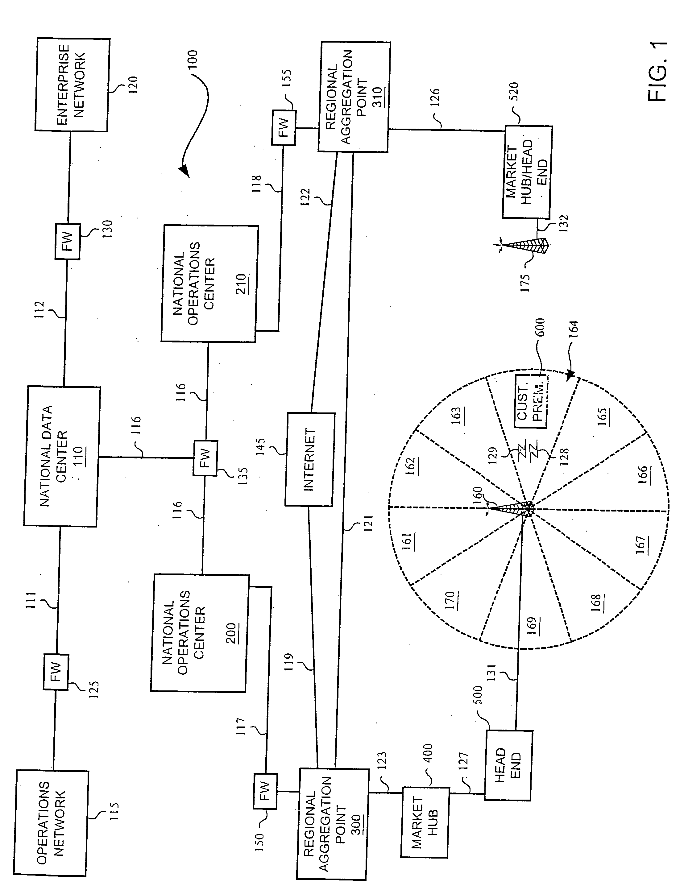
[0052]FIG. 1 is a block diagram that illustrates a broadband wireless system 100 in an example of the invention. The broadband wireless system 100 is comprised of a national data center 110, an operations network 115, an enterprise network 120, a national operations center 200, a national operations center 210, an Internet 145, a regional aggregation point 300, a regional aggregation point 310, a market hub 400,...


PUM


Abstract

A wireless communication system controls wireless communications over a shared wireless link. The wireless communication system transfers first credits to a first wireless communication device at a first credit transmission rate. The wireless communication system transfers second credits to a second wireless communication device at a second credit transmission rate. The first credits indicate first time periods for the first wireless communication device to use the shared wireless link. The second credits indicate second time periods for the second wireless communication device to use the shared wireless link. The wireless communication system changes the first credit transmission rate and changes the second credit transmission rate. In some examples, the wireless communication system changes the first credit transmission rate and the second credit transmission rate in response to collisions on the shared wireless link.

Description

RELATED APPLICATIONS [0001] This patent application is a continuation of U.S. patent application Ser. No. 09 / 981,173, that is entitled “ACCESS BASED ON TERMINATION IN A WIRELESS COMMUNICATION SYSTEM,” that was filed on Oct. 17, 2001, and that claims the benefit of U.S. Provisional Patent Application 60 / 241,048, that is entitled “BROADBAND WIRELESS COMMUNICATION SYSTEM,” and that was filed on Oct. 17, 2000. U.S. patent application Ser. No. 09 / 981,173 and U.S. Provisional Patent Application 60 / 241,048 are hereby incorporated by reference into this patent application.FEDERALLY SPONSORED RESEARCH OR DEVELOPMENT [0002] Not applicable MICROFICHE APPENDIX [0003] Not applicable BACKGROUND OF THE INVENTION [0004] 1. Field of the Invention [0005] The invention is related to the field of communication systems, and in particular, to a wireless communication system that determines access to wireless communications. [0006] 2. Description of the Prior Art [0007] People and businesses are demanding...

Claims


Application Information

Patent Timeline
Patent Type & Authority Applications(United States)
IPC IPC(8): H04J3/22
CPCH04W28/20H04W72/1278H04W72/1252H04W72/52H04W72/20
Inventor DISPENSA, STEVESLODERBECK, JASON M.
Owner SPRINT CORPORATION
Why Eureka
Try Eureka