Rotary connector

a technology of rotary connectors and connectors, applied in the direction of current collectors, electric/fluid circuits, vehicle components, etc., can solve the problems of abnormal noise and difficulty in accurately molding parts, and achieve the effect of reducing manufacturing costs

Active Publication Date: 2006-03-16
ALPS ALPINE CO LTD
View PDF13 Cites 12 Cited by
  • Summary
  • Abstract
  • Description
  • Claims
  • Application Information

AI Technical Summary

Benefits of technology

[0008] Accordingly, the invention has been made to solve the above-mentioned problems, and it is an object of the invention to provide a rotary connector in which position regulating portions of the movable-side housing can be accurately molded with resin with respect to the fixed-side housing and abnormal noise does not occur despite deformation caused by temperature variation and variation per hour.

Problems solved by technology

However, the conventional rotary connector has the following problems: Since the conventional rotary connector is formed by injection molding of insulating resin, it is difficult to accurately mold a portion, which is away from a rotation axis in a radial direction thereof, with resin.
Therefore, abnormal noise occurs.

Method used


Image

  • Rotary connector
  • Rotary connector
  • Rotary connector

Examples


first embodiment

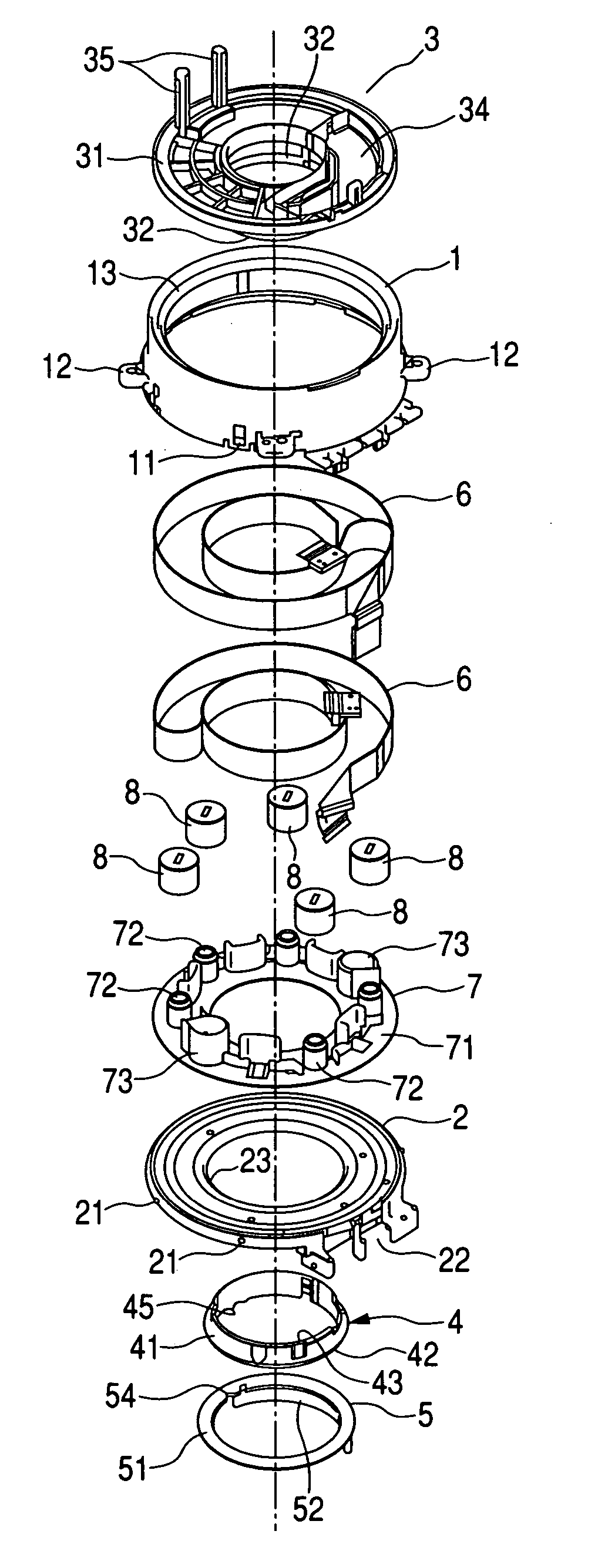
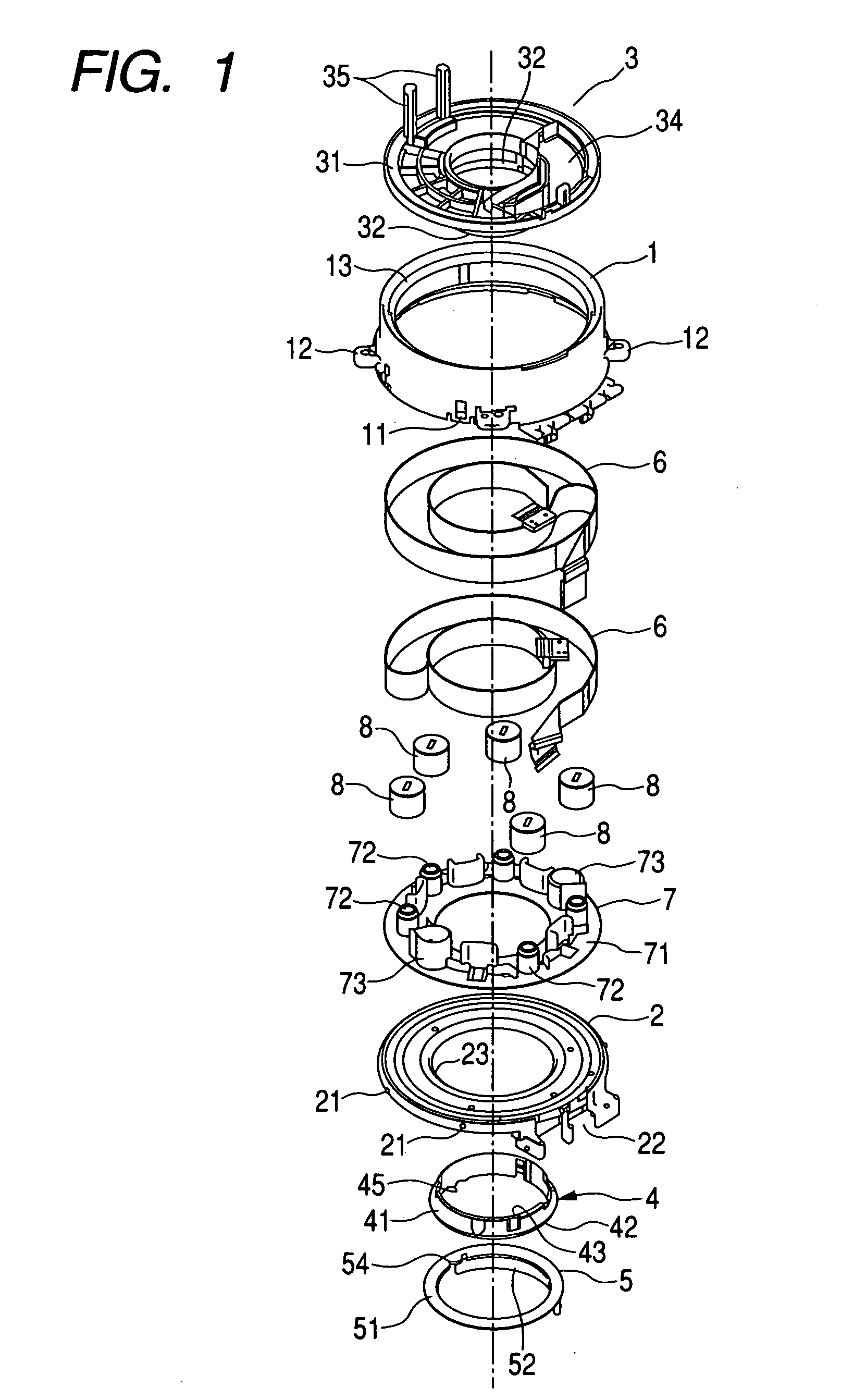
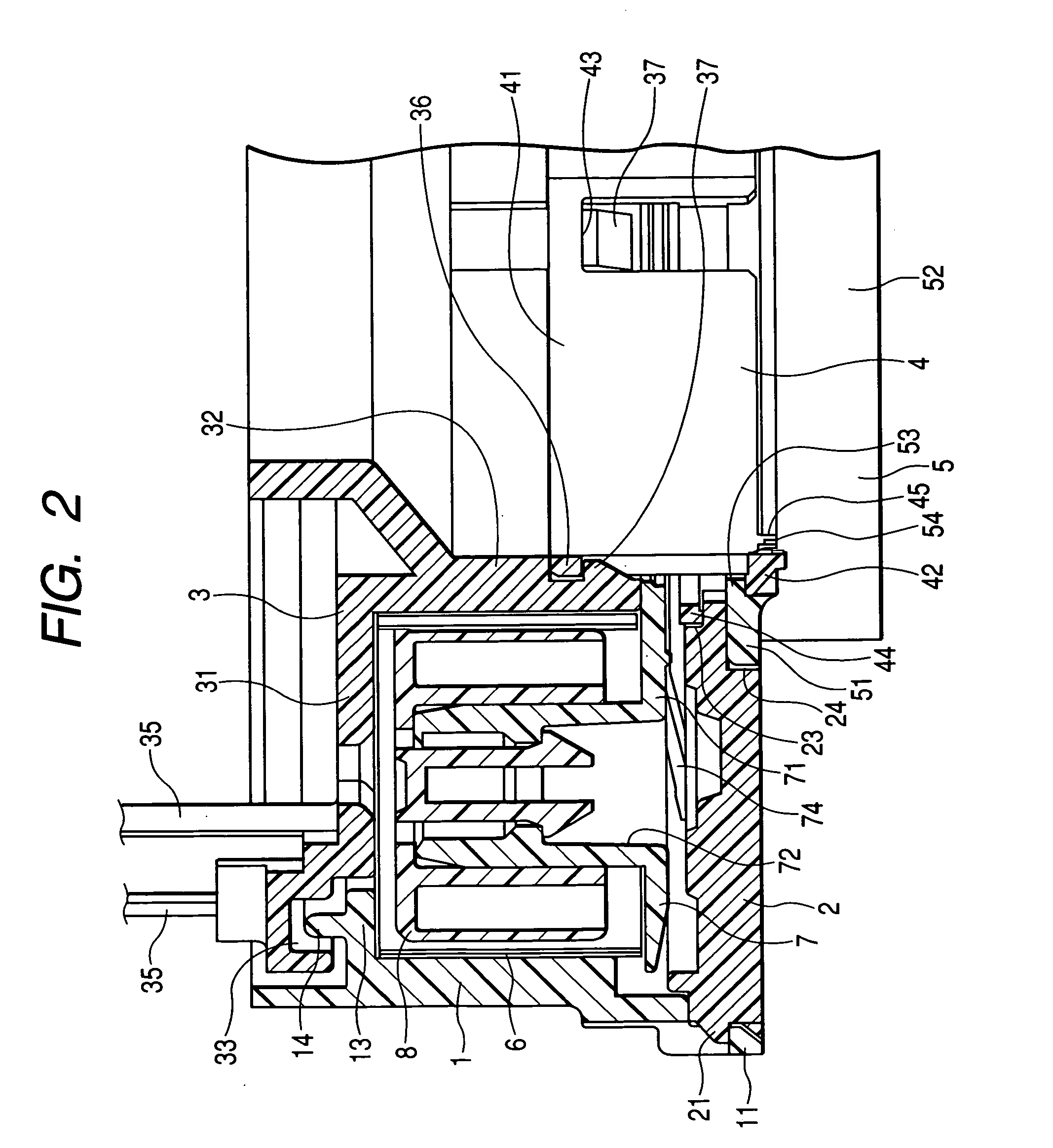
[0033] Hereinafter, a rotary connector according to the invention will be described with reference to FIGS. 1 and 2. FIG. 1 is an exploded perspective view showing a rotary connector according to the present embodiment, and FIG. 2 is a cross-sectional view showing main parts of the rotary connector according to the present embodiment.

[0034] As shown in FIG. 1, the rotary connector according to the present embodiment is mainly composed of a case 1, a cover 2, a rotor (movable-side housing) 3, a rotor snap 4, a cancel member 5, flexible cables 6, a ring-shaped holder 7, and rollers 8. Every member other than the flexible cables 6 is made of insulating resin.

[0035] The case 1 is formed in a cylindrical shape having a required size, and first engaging parts 11 for snap-fitting the cover 2 and mounting bosses 12 for fixing the case 1 to a stator part of a vehicle are formed on the lower side of an outer circumferential surface of the case 1. Furthermore, an annular protrusion 13 protrud...

second embodiment

[0061] In the rotary connector the inner rim of the cover 2 is interposed between the holding projection 44 and the ring-shaped plate part 51 with a small clearance, and a side surface of the ring-shaped plate part 51 faces a wall surface forming the step of an engaging step 24 with a small clearance. Therefore, it is possible to simultaneously regulate an axial position and a radial position of the movable-side housing with respect to the fixed-side housing by a portion close to a rotation axis of the rotor (movable-side housing) 3, and to accurately mold the position regulating portions with resin. Moreover it is possible to reduce deformation caused by temperature variation and variation per hour. For this reason, it is possible to suppress occurrence of abnormal noise during the rotation of the movable-side housing.

[0062] Furthermore, in the rotary connector according to the second embodiment, since the engaging step 24 is formed on the inner rim of the lower surface of the cov...

third embodiment

[0065] In the rotary connector as shown in FIG. 4, a holding step 23 capable of receiving an outer circumferential surface of holding projection 44 which is formed on a rotor snap 4 is formed on an inner rim of an upper surface of the cover 2 instead of forming an engaging step 24 on an inner rim of a lower surface of the cover 2, as shown in FIG. 3.

[0066] A wall surface forming a step of the holding step 23 is formed so as to face the side surface of the holding projection 44 formed on the rotor snap 4 with a small clearance when the cover 2 and the rotor snap 4 are assembled with each other. In addition, a wall surface forming a step of the holding step 23 is formed so that an inner rim of the cover 2 is interposed, with a small clearance, between the lower surface of the holding projection 44 formed on the rotor snap 4 and a ring-shaped plate part 51 included in the cancel member 5 when the cover 2, the rotor snap 4, and a cancel member 5 are assembled with each other.

[0067] In...


PUM


Abstract

A rotary connector includes a case, a cover, a rotor having a top panel part and a first cylindrical part, a rotor snap having locking parts locked with an outer surface of the cover and a second cylindrical part snap-fitted to the first cylindrical part, flexible cables wound windably / rewindably in the case, and a ring-shaped plate part. In this case, a holding projection project outward in a radial direction from the outer circumferential surface of the second cylindrical part between a lower end of the first cylindrical part and the locking parts, and an inner rim of the cover is provided with a holding step so as to form a step. Furthermore, a wall surface forming the step of the holding step faces side surface of the holding projection, and an inner rim of the cover is rotatably interposed between lower surface of the holding projection and an upper surface of the ring-shaped plate part.

Description

BACKGROUND OF THE INVENTION [0001] 1. Field of the Invention [0002] The present invention relates to a rotary connector which electrically connects an electrical device provided in a steering wheel with an electrical device provided in a vehicle, and more particularly, to a structure of connecting a fixed-side housing with a movable-side housing. [0003] 2. Description of the Related Art [0004] A conventional rotary connector has been known before (for example, Japanese Unexamined Patent Application Publication No. 2003-174715). As shown FIG. 5, the conventional rotary connector includes a fixed-side housing 103 that includes a cylindrical case 101 and a ring-shaped cover 102 for covering one end of the case 101; a movable-side housing 106 that includes a ring-shaped top panel part 104 for covering the other end of the case 101 and a first cylindrical part 105 rising downward from an inner circumferential end of the top panel part 104; a rotor snap 110 that includes a ring-shaped loc...

Claims


Application Information

Patent Timeline
Patent Type & Authority Applications(United States)
IPC IPC(8): H01R39/00
CPCB60R16/027
Inventor ARAKI, SHUNJITAKAHASHI, SEISHIITO, KAZUHIKO
Owner ALPS ALPINE CO LTD
Why Eureka
Try Eureka