Plastic molding die

a plastic molding and die technology, applied in the field of plastic molding dies, can solve the problems of poor inability to apply methods to products, and complex dies, and achieve the effect of improving the molding accuracy of plastic materials

a plastic molding and die technology, applied in the field of plastic molding dies, can solve the problems of poor inability to apply methods to products, and complex dies, and achieve the effect of improving the molding accuracy of plastic materials

US7845934B2Inactive Publication Date: 2010-12-07FUJIFILM CORP +1

Image

  • Plastic molding die
  • Plastic molding die
  • Plastic molding die

Examples


Embodiment Construction

[0038]Next, an embodiment of the present invention will be explained in detail by referring to figures.

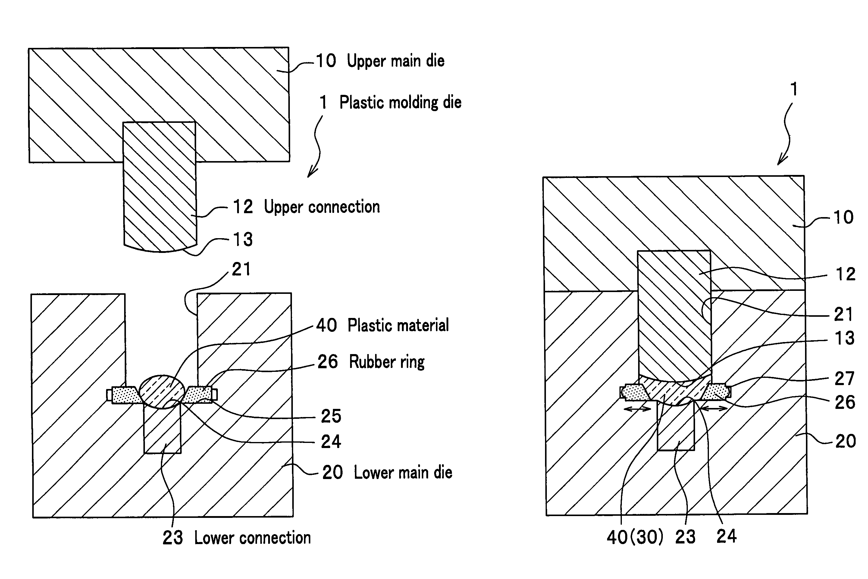
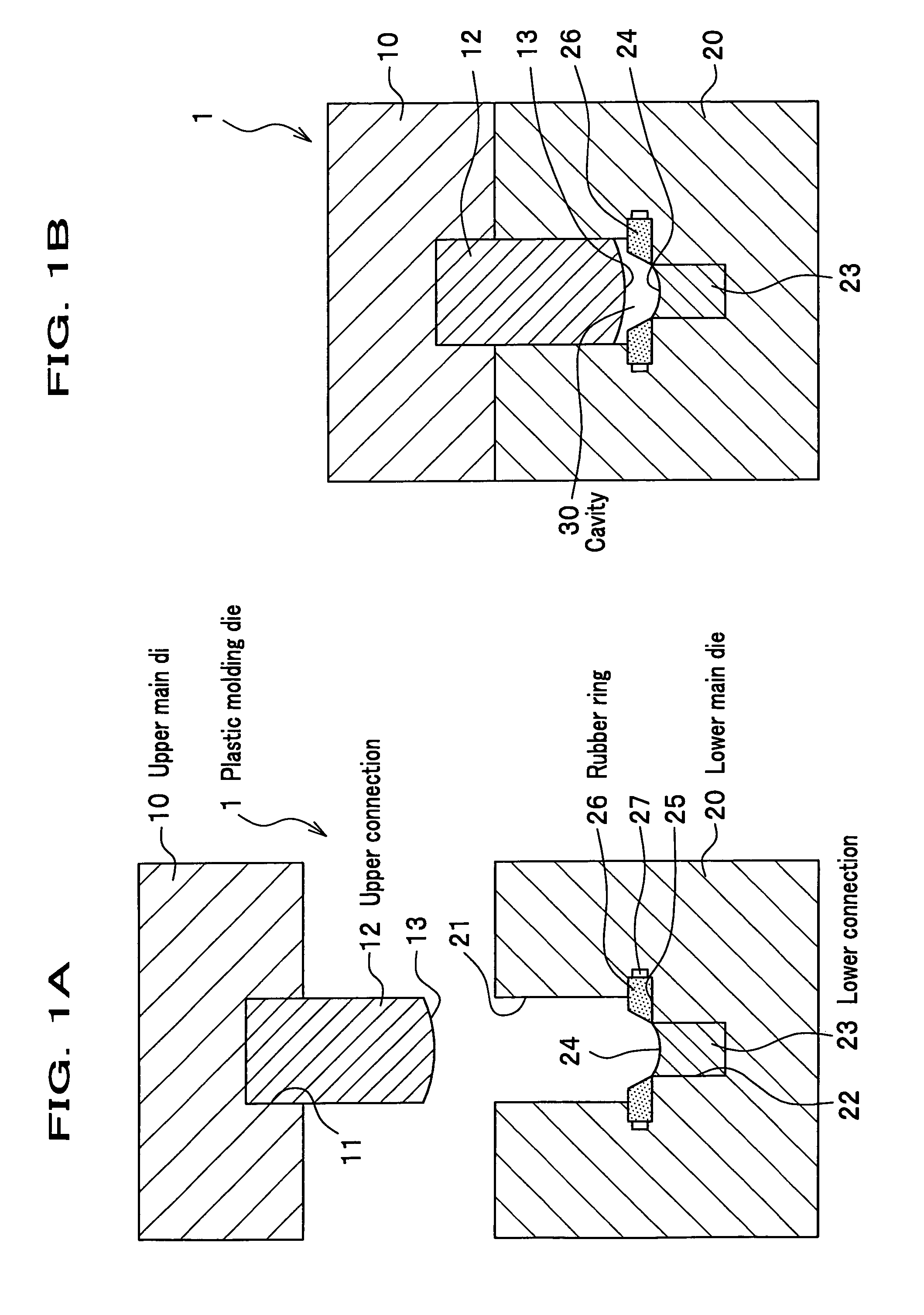
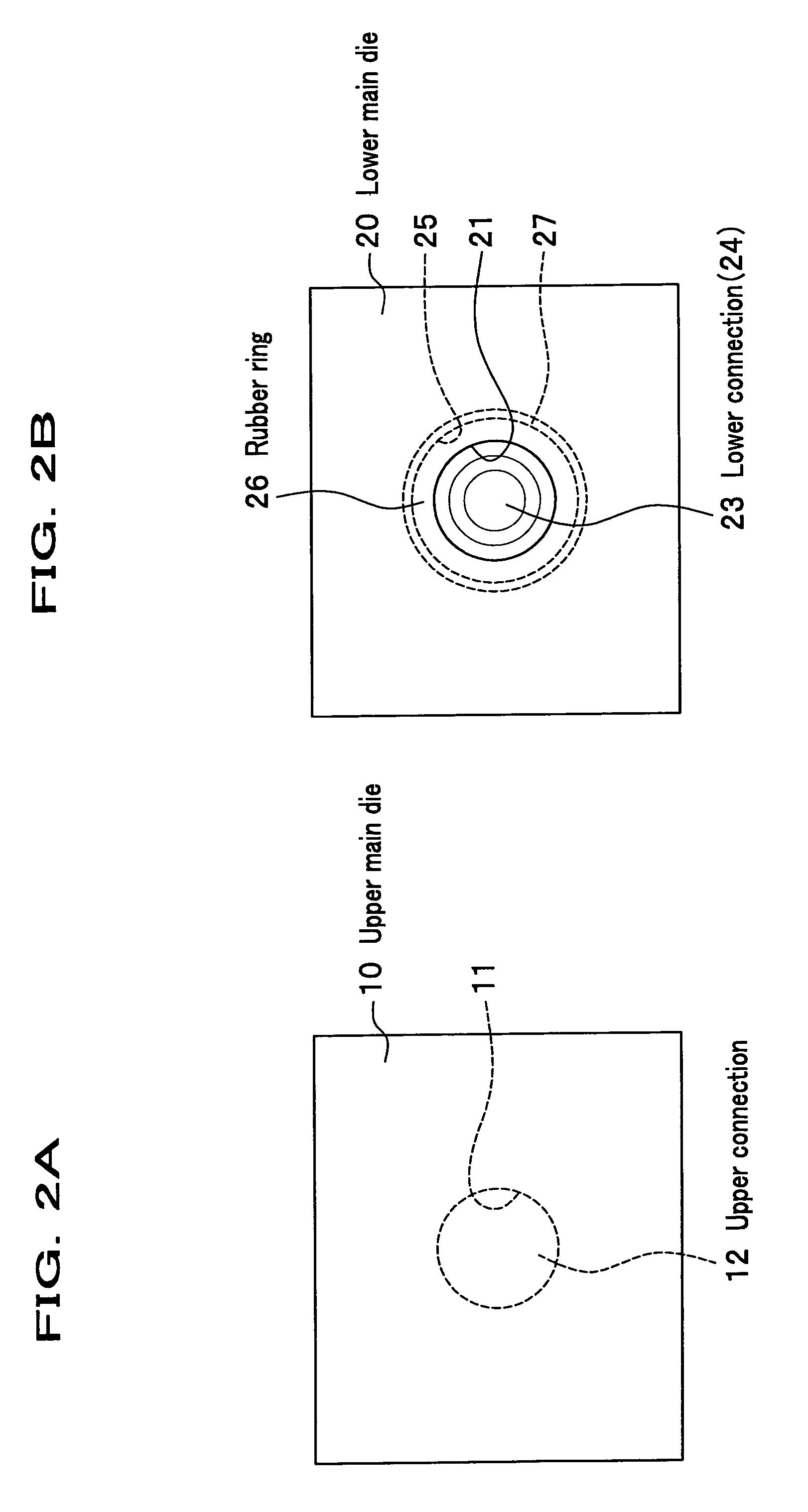
[0039]FIGS. 1A and 1B are views showing a plastic molding die according to an embodiment of the present invention. FIG. 1A is a side cross sectional view showing each main die being separated to each other, of a plastic molding die according to the embodiment. FIG. 1B is a side cross sectional view showing each main die being engaged with each other, of the plastic molding die according to the embodiment. FIGS. 2A and 2B are views showing the plastic molding die according to the embodiment. FIG. 2A is a plane view showing an upper main die of the plastic molding die according to the embodiment. FIG. 2B is a plane view showing a lower main die of the plastic molding die according to the embodiment.

[0040]In the embodiment, an example for manufacturing a plastic lens with compression molding of a plastic material will be used for explaining the present invention.

(Configuration of Plas...


PUM

PropertyMeasurementUnit
elastic deformationaaaaaaaaaa
elasticityaaaaaaaaaa
glass-transition temperatureaaaaaaaaaa

Abstract

A plastic molding die provided with a cavity where a plastic material is put in, wherein a part of an inner surface of the cavity is configured with an elastic body. A molding portion corresponding to a molding surface of a molded product is disposed on the inner surface of the cavity, and the elastic body is arranged on a portion other than the molding portion of the inner surface of the cavity. The plastic molding die may be a molding die for compression molding. The elastic body is made of rubber, and has an upper temperature limit higher than a glass-transition temperature of the plastic material. The degree of rubber hardness of the elastic body is from 50 to 100.

Description

CROSS REFERENCE TO RELATED APPLICATIONS[0001]This application claims the foreign priority benefit under Title 35, United States Code, §119(a)-(d) of Japanese Patent Application No. 2005-011769, filed on Jan. 19, 2005, the contents of which are hereby incorporated by reference.BACKGROUND OF THE INVENTION[0002]1. Technical Field of the Invention[0003]The present invention relates to a plastic molding die for molding a plastic material.[0004]2. Description of the Related Art[0005]As a plastic molding die for manufacturing a plastic lens with compression molding, using a plastic material, there is a plastic molding die which is configured so that a cavity is formed between each connection mounted on each main die of the plastic molding die when the each main die, an upper main die and a lower main die, is combined to each other.[0006]In the plastic molding die, a plastic material is put in a space between the connections mounted on each main die when the each main die is separated to ea...

Claims


Application Information

Patent Timeline
07 Dec 2010
Publication
US7845934B2
IPC
B29D11/00; B29C33/50
CPC
B29C33/18; B29C41/003; B29C41/20; B29C43/021; B29C43/18; B29C43/361; B29C45/572; B29C2043/3618
Inventors
SUZUKI, FUMIYUKI; MOCHIZUKI, TADASHI