Minute shape molding method and apparatus thereof

a technology of molding method and minute shape, which is applied in the direction of dough shaping, manufacturing tools, other chemical processes, etc., can solve the problems of long molding time of the product, time required to heat the die that has been cooled, and it is not desirable to heat the die partially to a high temperature, so as to shorten the molding cycle of the product

Inactive Publication Date: 2010-10-26
TOSHIBA MASCH CO LTD
View PDF10 Cites 1 Cited by
  • Summary
  • Abstract
  • Description
  • Claims
  • Application Information

AI Technical Summary

Benefits of technology

[0008]An object of the present invention is to solve the problem described above, and provide a minute shape molding method by which a molding cycle of the product can be shortened, and the minute shape can be accurately molded in a molding method in which after a resin is injected, die clamping is performed again, and an apparatus thereof.
[0011]Accordingly, it is possible to shorten the time required to raise the die temperature to a predetermined temperature state necessary for molding and, even by the molding method in which clamping of the die is performed twice, it is possible to shorten the molding cycle of the product. The transcription die is heated by the heating unit, and hence it is possible to heat the die efficiently and in an accurate temperature state, and mold a product having a minute uneven shape with a high degree of accuracy.

Problems solved by technology

However, in order to mold a product along a minute uneven shape formed on the molding surface of a die, it is necessary to inject a resin into the inside of the cavity of the die at high pressure.
However, in the molding method described above, there has been a problem that after the resin is injected into the die, the die is clamped again, and thus the molding time of the product becomes long.
Further, in order to form a minute uneven shape, it is necessary to accurately set the temperature of the die, and thus the time required to heat the die that has been cooled to solidify the product to a predetermined temperature for the next molding has been long.
That is, it is not desirable to heat the die partially to a high temperature in order to raise the temperature of the die within a short time.

Method used


Image

  • Minute shape molding method and apparatus thereof
  • Minute shape molding method and apparatus thereof
  • Minute shape molding method and apparatus thereof

Examples


Embodiment Construction

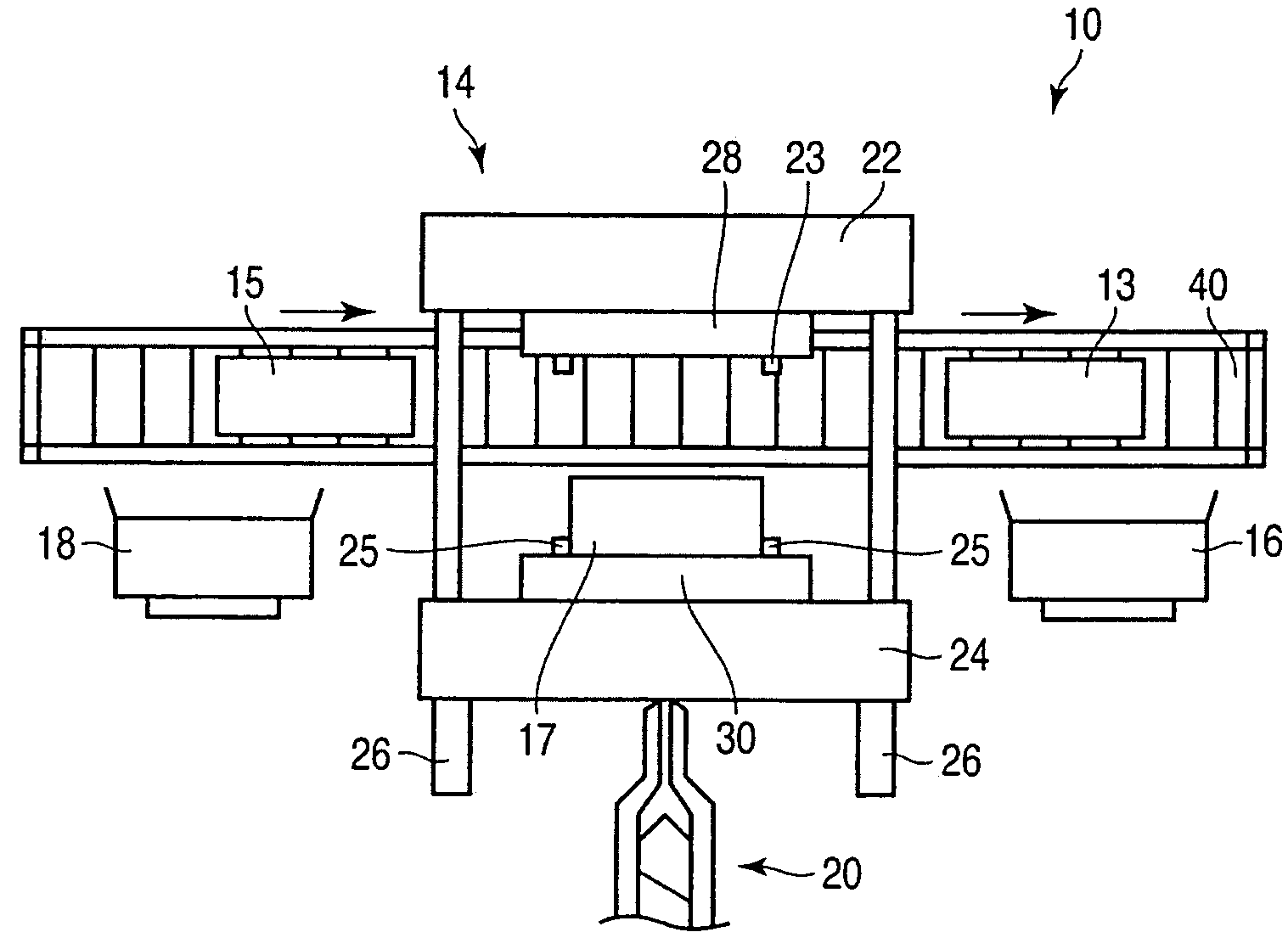
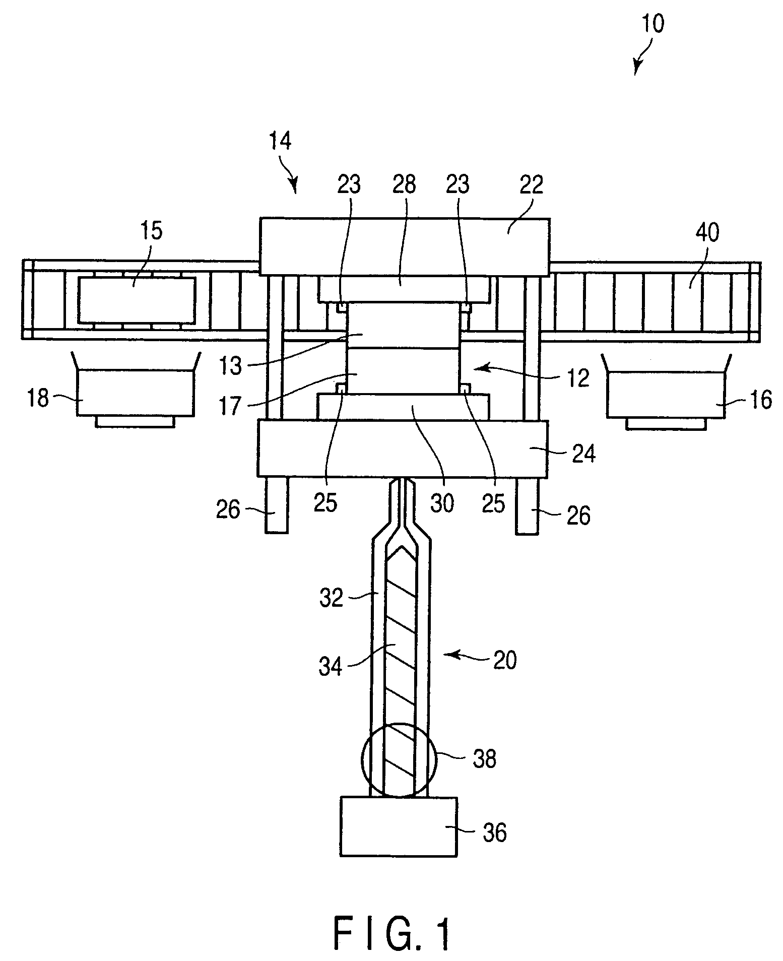
[0024]An embodiment of a molding equipment according to the present invention will be described below with reference to the accompanying drawings. The molding equipment 10 is constituted of, as shown in FIG. 1, a die 12, a clamping mechanism 14, heating units 16 and 18 provided on both sides of the clamping mechanism 14, an injection mechanism 20, and the like. FIG. 1 is a plan view of the molding equipment 10.

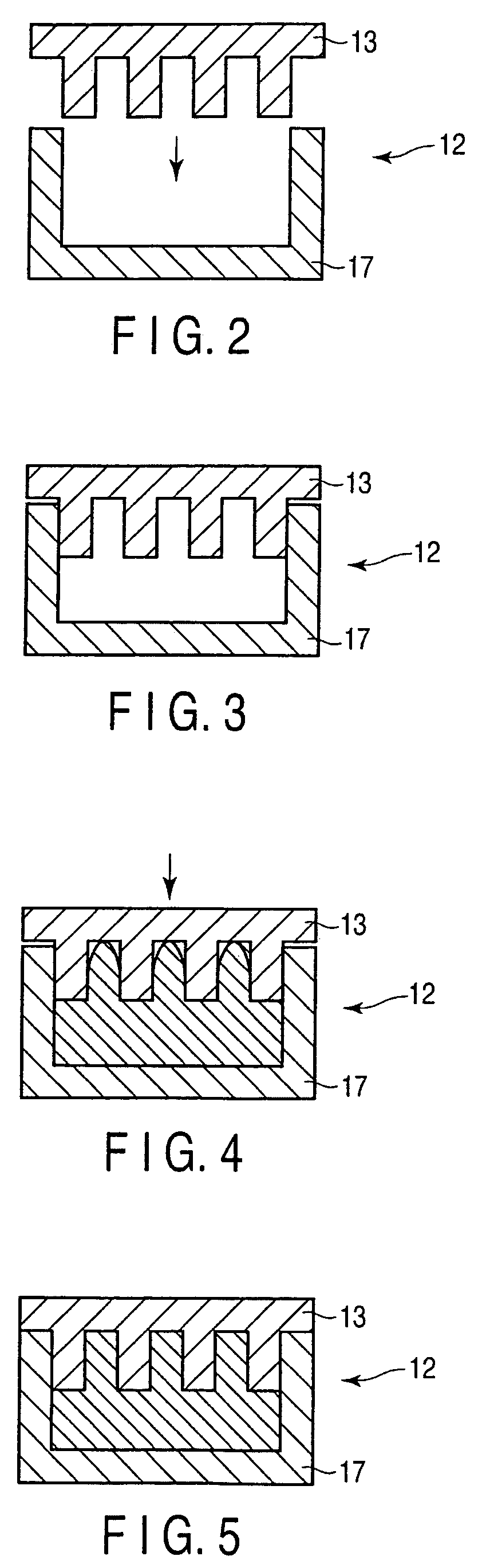
[0025]The die 12 is constituted of a pair of dies opposed to each other, and is formed of a first die 13 (which is a “transcription die”) having an uneven section of a minute shape in the cavity, and a third die 17 to be paired with the first die 13. Further, a second die 15 having the same shape as the first die 13 is positioned on the left side in FIG. 1, and the second die 15 is also paired with the third die 17 to thereby constitute a paired die 12. The uneven section formed on the first die 13 or the second die 15 is a part having a minute shape with a thickness of about ...


PUM

PropertyMeasurementUnit
thicknessaaaaaaaaaa
shapeaaaaaaaaaa
temperatureaaaaaaaaaa

Abstract

A method of molding a minute shape, in which at least one of a pair of dies is provided with an uneven section of a minute shape on a molding surface thereof, clamping of the pair of dies is stopped immediately before the dies are completely clamped, a resin is injected into a cavity, and thereafter the dies are completely clamped to thereby transcribe the shape of the uneven section onto the resin includes preparing a plurality of transcription dies each provided with the uneven section on a molding surface thereof, heating one of the transcription dies which is not used to mold a product by a heating unit, and exchanging the transcription dies with each other, at a point in time at which molding is completed, to thereby mold the product continuously.

Description

CROSS-REFERENCE TO RELATED APPLICATIONS[0001]This application is based upon and claims the benefit of priority from prior Japanese Patent Application No. 2007-288853, filed Nov. 6, 2007, the entire contents of which are incorporated herein by reference.BACKGROUND OF THE INVENTION[0002]1. Field of the Invention[0003]The present invention relates to a method of molding a minute shape by injection molding, and an apparatus thereof.[0004]2. Description of the Related Art[0005]A method of molding a product having a minute uneven shape on the surface, such as an optical component by using a die has been used in recent years. However, in order to mold a product along a minute uneven shape formed on the molding surface of a die, it is necessary to inject a resin into the inside of the cavity of the die at high pressure. Therefore, a molding method is known in which the clamping operation of the die is stopped directly before the die is completely clamped, the resin is injected into the insi...

Claims


Application Information

Patent Timeline
Patent Type & Authority Patents(United States)
IPC IPC(8): B29C45/04
CPCB29C45/372B29C45/561B29C45/73B29C45/04Y10S264/65
Inventor TAKEMOTO, ATSUSHIKOIKE, JUN
Owner TOSHIBA MASCH CO LTD
Why Eureka
Try Eureka