A mold assembly tool for a single blade wax mold of a turbine guide

A turbine guider and single-blade technology, which is applied in the direction of casting and molding equipment, can solve the problems of high mold maintenance costs, small mold parts, and many sharp edges

Active Publication Date: 2021-09-14
成都晨发泰达航空科技股份有限公司
View PDF0 Cites 1 Cited by
  • Summary
  • Abstract
  • Description
  • Claims
  • Application Information

AI Technical Summary

Problems solved by technology

[0004] For the form of integral mold opening, the design is difficult, the gap between the blades is small, the mold parts between the blades are too small, and there are many sharp edges, which will cause the mold to be damaged quickly and the mold maintenance cost is high later.
At the same time, for guides with cavities, there is a high probability of breaking the ceramic core during the process of wax pressing. However, for guides used in the whole ring, any breakage of the ceramic core will cause the whole ring to be scrapped, and the overall mold opening cost is too high

Method used


Image

  • A mold assembly tool for a single blade wax mold of a turbine guide
  • A mold assembly tool for a single blade wax mold of a turbine guide
  • A mold assembly tool for a single blade wax mold of a turbine guide

Examples


Embodiment 1

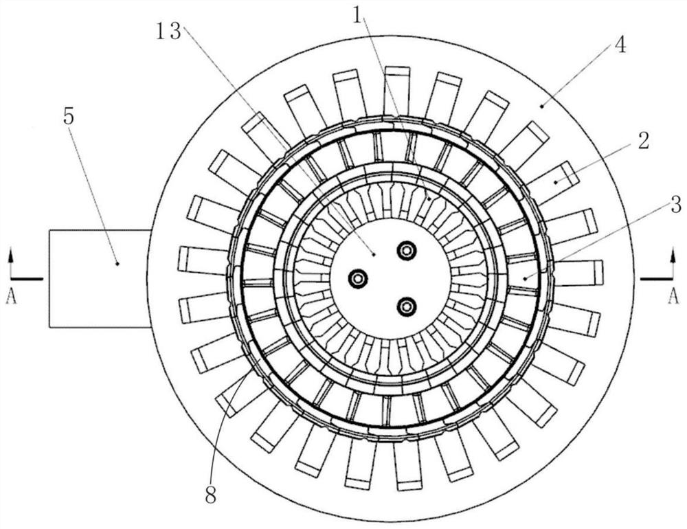
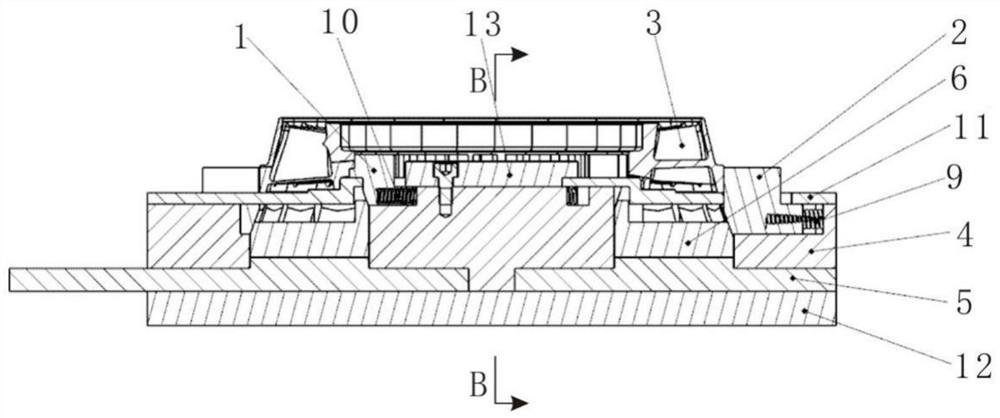
[0033] Such as figure 1 As shown, the mold assembly tooling of the single blade wax mold 3 of the turbine guider includes the wax mold 3 cooperatingly sandwiched between the inner positioning block 1 and the outer positioning block 2, and the wax mold is fixed by the inner positioning block 1 and the outer positioning block 2 respectively. The two ends of the mold 3 are clamped to complete the fixing of the position of the wax mold 3 .

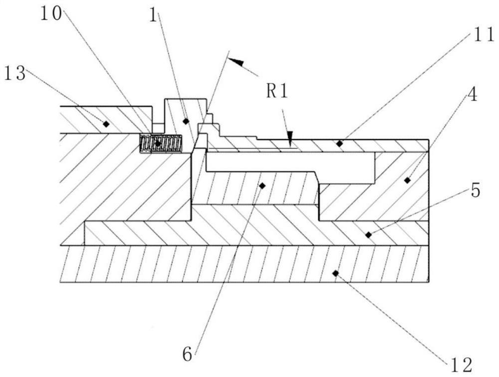
[0034] Wherein, the inner positioning block 1 and the outer positioning block 2 are installed on the track base 4, and can move horizontally relative to the track base 4, thereby realizing clamping, positioning and release of the wax mold 3. Preferably, a chute is installed on the track base 4 , and the length direction of the chute is set relative to the clamping direction of the wax model 3 .

[0035] The track base 4 has a guiding and limiting effect on the inner positioning block 1 and the outer positioning block 2. It adopts an integral ...

Embodiment 2

[0047] According to an embodiment of the present application, on the basis of the above embodiments, a U-shaped ring groove 7 is provided on the track base 4 .

[0048] Wherein, the ejection structure 6 is placed in the U-shaped ring groove 7, and moves up and down in the U-shaped ring groove 7. Through the setting of the U-shaped ring groove 7, the moving direction of the ejection structure 6 is limited. Only the degree of freedom in the vertical direction is left, so that in the process of rotating the handle 5, the up and down movement of the ejection structure 6 in the U-shaped ring groove 7 can be effectively driven, which provides a structural basis for use and stable performance.

[0049] It can be preferably designed that there are two helical surface projections at a distance of 180° at the top of the rotating handle 5, and the helical surface projections cooperate with the helicoid projections arranged at the bottom of the ejection structure 6, and the helical surfac...

Embodiment 3

[0052] The inner positioning block 1 and the outer positioning block 2 of the molding tooling of the single blade wax mold 3 of the turbine guide both clamp the wax mold 3 through the arc groove structure 8 .

[0053] Specifically, an inner ring positioning groove is arranged on the inner side of the wax mold 3, and an outer ring positioning groove is arranged on the outer side of the wax mold 3. The inner ring positioning groove of the wax mold 3 is aligned with the inner positioning block 1, and the wax The positioning groove of the outer ring of the mold 3 and the outer positioning block 2 are aligned and clamped.

[0054] There are multiple inner positioning blocks 1 and outer positioning blocks 2, and both the inner positioning blocks 1 and the outer positioning blocks 2 are distributed in a ring shape; during operation, place the rotation handle 5 at the limit position counterclockwise, and pull the outer positioning blocks outward 2. After putting the wax mold 3 in plac...


PUM


Abstract

The invention discloses a mold-assembling tooling for a turbine guider single-blade wax mold, which comprises a wax mold fitted between an inner positioning block and an outer positioning block, the inner positioning block and the outer positioning block are installed on a track base, And it can move horizontally relative to the track base to clamp, position and release the wax mold; the non-clamping ends of the inner and outer positioning blocks are connected with the elastic mechanism to realize the inner and outer positioning blocks The elastic clamping and reset of the track base; the lower end of the track base is equipped with a rotating handle, which can rotate around the axis; the track base is equipped with an ejection structure that can move up and down. The structure is in contact with the inner positioning block and the outer positioning block in the form of an inclined surface, and the ejection structure and the rotating handle are in contact with a helical surface, and the ejecting structure moves up and down under the rotation of the rotating handle. The mold set tool can accurately and efficiently combine a group of individual blade wax patterns into a full ring guide wax pattern.

Description

technical field [0001] The invention relates to the fields of aerodynamic devices and gas turbine guides, in particular to a tool for forming a single-blade wax model of a turbine guide. Background technique [0002] Turbine guide is an important high-temperature part of aerodynamic power plant and gas turbine. It is located behind the combustion chamber and before the turbines at all levels to withstand the impact of high-temperature and high-pressure gas. [0003] At present, the turbine guide is composed of an inner ring, an outer ring and multiple blades, and is produced by precision investment casting. The initial process of the casting process is to make a wax mold module. Now the wax mold manufacturing generally includes the overall mold opening and a single blade. Mold. [0004] For the form of integral mold opening, the design is difficult, the gap between the blades is small, the mold parts between the blades are too small, and there are many sharp edges, which wi...

Claims


Application Information

Patent Timeline
Patent Type & Authority Patents(China)
IPC IPC(8): B22C7/02
CPCB22C7/02
Inventor 胡敏赵俊伟史鹏飞
Owner 成都晨发泰达航空科技股份有限公司
Why Eureka
Try Eureka