Mold for glass

a mold and glass technology, applied in the field of molds, can solve the problems of shortened useful life of molds, conventional glass shaping techniques, and reduced mold life, and achieve the effect of long li

Inactive Publication Date: 2007-08-16
KINIK
View PDF3 Cites 0 Cited by
  • Summary
  • Abstract
  • Description
  • Claims
  • Application Information

AI Technical Summary

Benefits of technology

[0012] The main objective of the present invention is to provide a mold for gl

Problems solved by technology

However, the first conventional technique for shaping glass is disadvantage for providing glass with aspheric surfaces.
Because the upper mold (1) and the lower mold (2) contact with the glass (3) at high temperature during the processes of shaping glass, such that the surfaces of the upper mold (1) and the low

Method used


Image

  • Mold for glass
  • Mold for glass
  • Mold for glass

Examples


Embodiment Construction

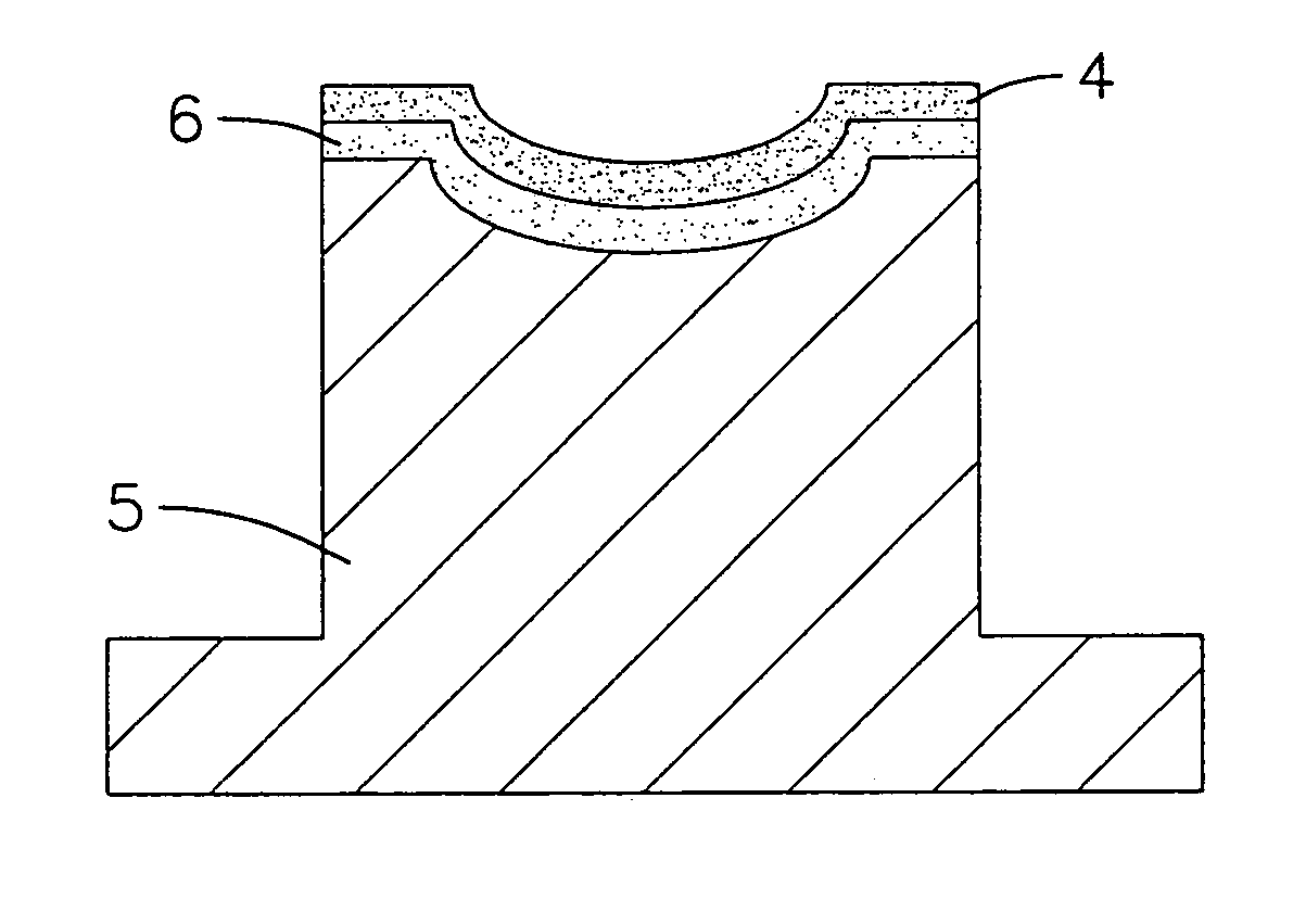
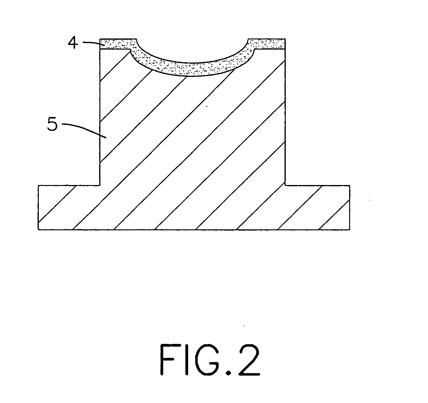
[0017] With reference to FIGS. 2, a first preferred embodiment of the present invention has a diamond protective film (4) and a base (5). The diamond protective film (4) is provided by deposition technique and substantially made of pure diamond. The base (5) is made of ceramic materials such as carborundum, silicon nitride, aluminium nitride, silicide, etc, which has the same expansion rate as that of the diamond protective film (4).

[0018] The base (5) has a top recess defined in the top and having a desired shape such as a spherical inner surface. The diamond protective film (4) is coated onto the top recess in the base (5) with deposition technique. The diamond protective film (4) has 0.2-40 μm in thickness. When the thickness of the diamond protective film (4) is much than 40 μtm, the diamond protective film (4) is easy to separate from the base (5). When the thickness of it is less than 0.2 μm, the diamond protective film (4) can not provide an enough protecting effect to the b...


PUM

PropertyMeasurementUnit
Temperatureaaaaaaaaaa
Surface roughnessaaaaaaaaaa
Expansion enthalpyaaaaaaaaaa

Abstract

A mold for glass has a base and a diamond protective film deposited on the base. Due to the quality of the diamond protective film, the base can be protected substantially with a high temperature in the process of manufacturing the glass to extend the lifespan of the mold.

Description

BACKGROUND OF THE INVENTION [0001] 1. Field of the Invention [0002] The present invention relates to a mold for, and more particularly to a mold for glass and that has a diamond film mounted thereon. [0003] 2. Description of the Related Art [0004] A first conventional technique for shaping glass is a step of grinding, polishing and cleaning. However, the first conventional technique for shaping glass is disadvantage for providing glass with aspheric surfaces. [0005] A second conventional technique for shaping glass is used with a mold. With reference to FIGS. 1, the second conventional technique for shaping glass comprises an upper mold (1) and a lower mold (2) detachably combined with the upper mold (1). Glass (3) is provided between the upper mold (1) and the lower mold (2). The glass (3) is heated to soften and then is compressed by the upper mold (1) and the lower mold (2) to form a desired shape. When the temperature of the glass (3) is lowered, the glass (3) has a desired shap...

Claims


Application Information

Patent Timeline
IPC IPC(8): C03B11/08C03B7/14
CPCC03B11/086C03B2215/12C03B2215/17C03B2215/66C03B2215/26C03B2215/30C03B2215/24
Inventor LIAO, WEN-JENHUANG, JEN-SHEUANCHANG, HSIAO-KUO
Owner KINIK
Why Eureka
Try Eureka