[0013] The object of the present invention is to provide a power supply control apparatus and a power supply control method capable of realizing
power saving by ingeniously designing only an apparatus on the power supplying side without particularly modifying the conventional configuration of a communication terminal on the power receiving side.
[0015] In the first aspect of the present invention, the power supply control apparatus comprises one or a plurality of connectors, each provided with a plurality of connection terminals and part or all of the connection terminals being power supply terminals for supplying power to communication apparatuses to be connected.
Time zone data indicating time zones during which the power supply terminals should stop power supply is stored so as to correspond to the respective connectors. Then, for respective power supply terminals of the connector, the time data output from the
clock is compared with the corresponding time zone data stored, and power supply is turned ON / OFF depending on the result of the comparison. Hence, power supply to the connected communication apparatuses to which power is to be supplied can be started and stopped according to a predetermined schedule, without intermittently supplying power to the communication apparatuses. For example, a communication apparatus consumes power continuously to stand by for reception in many cases. However, in the case that it is predicted that reception is not performed or in the case that there is a time period during which it is determined that no reception is performed, even if power is supplied during the time period, there is a high possibility that the power supply becomes wasteful. Since the time zone data indicating such a time zone is stored, unnecessary power supply can be reduced, and
power saving can be realized. In addition, this
power saving can be realized by ingeniously designing only the apparatus on the power supply control apparatus side. Hence, in the case that there are numerous communication terminals to be connected, the cost of the entire communication
system can be reduced when the above-mentioned power saving is realized.
[0017] In the second aspect of the present invention, the power supply control apparatus comprises one or a plurality of connectors, each provided with a plurality of connection terminals and part or all of the connection terminals being power supply terminals for supplying power to communication apparatuses to be connected. In addition, the power supply possible / impossible table for registering the possibility / impossibility of power supply in correspondence with the respective connectors. Furthermore, in the case of each connector registered to be “power supply impossible” in the power supply possible / impossible table, a
signal for confirming the connection of a communication apparatus to which power is to be supplied is applied to the power supply terminals of the connector. In the case of each connector registered to be “power supply possible,” a judgment is sequentially made as to whether power supply is performed or not. When it is confirmed that a communication apparatus to which power is to be supplied is connected, the content is renewed so as to indicate that the connection of the communication apparatus to the corresponding connector registered in the power supply possible / impossible table is present. When it is judged that power supply is not performed, the content is renewed so as to indicate that power supply is impossible. Furthermore, time zone data indicating non-power-supply time zones each serving as a time zone during which the respective power supply terminals of the corresponding connector should stop power supply is stored, and the time data is compared with the time zone data corresponding to the respective connectors registered to be “power supply possible” and power supply is turned ON / OFF according to the result of the comparison. On the other hand, for each connector registered to be “power supply impossible,” power supply using the connector is not performed. Hence, power is prevented from being supplied to an apparatus to which power is not to be supplied. Moreover, since power supply to the connected communication apparatuses to which power is to be supplied can be started and stopped according to a predetermined schedule, without intermittently supplying power to the communication apparatuses, power saving can be realized. Still further, this power saving can be realized by ingeniously designing only the apparatus on the power supply control side. Hence, in the case that there are numerous communication terminals to be connected, the cost of the entire communication
system can be reduced in the case of realizing the above-mentioned power saving.
[0019] In the third aspect of the present invention, power supply to each communication apparatus connected is stopped depending on the frequency in which power supply is required. The power supply control apparatus comprises one or a plurality of connectors, each provided with a plurality of connection terminals and part or all of the connection terminals being power supply terminals for supplying power to communication apparatuses to be connected. A
signal for confirming the connection of a communication apparatus to which power is to be supplied at predetermined timing is applied to the respective power supply terminals. When it is confirmed that a communication apparatus to which power is to be supplied is connected, power supply using the corresponding connector is started. In addition, a power threshold value and a time threshold value used as criteria according to which it is judged that the frequency in which power supply is required to a communication apparatus connected to each connector is lowered to the extent that no trouble occurs even if the power supply is stopped are stored beforehand in correspondence with the respective connectors. Furthermore, the power supply control apparatus is provided with the elapsed time measurement section for starting the measurement of elapsed time in correspondence with each connector to which power supply is started, and the power measurement value section for sequentially measuring the power value supplied at each connector. A judgment is made sequentially as to whether the power measurement value of the power measurement value section has reached the corresponding power threshold value or not. When it is judged that the power measurement value has reached the threshold value, the elapsed time measurement section is instructed to initialize the time measurement value for the corresponding connector and to restart the measurement. Then, a judgment is made sequentially as to whether each time measurement value has reached the corresponding time threshold value or not. When it is judged that the time measurement value has reached the threshold value, that is, when the state wherein it is judged that any one of the communication terminals does not require power supply continues for the period of time set as the time threshold value, power supply using the corresponding connector is stopped. Hence, it is possible to reduce unnecessary power supply to a communication terminal having a low or lowered frequency of power supply required, and power saving can be realized.
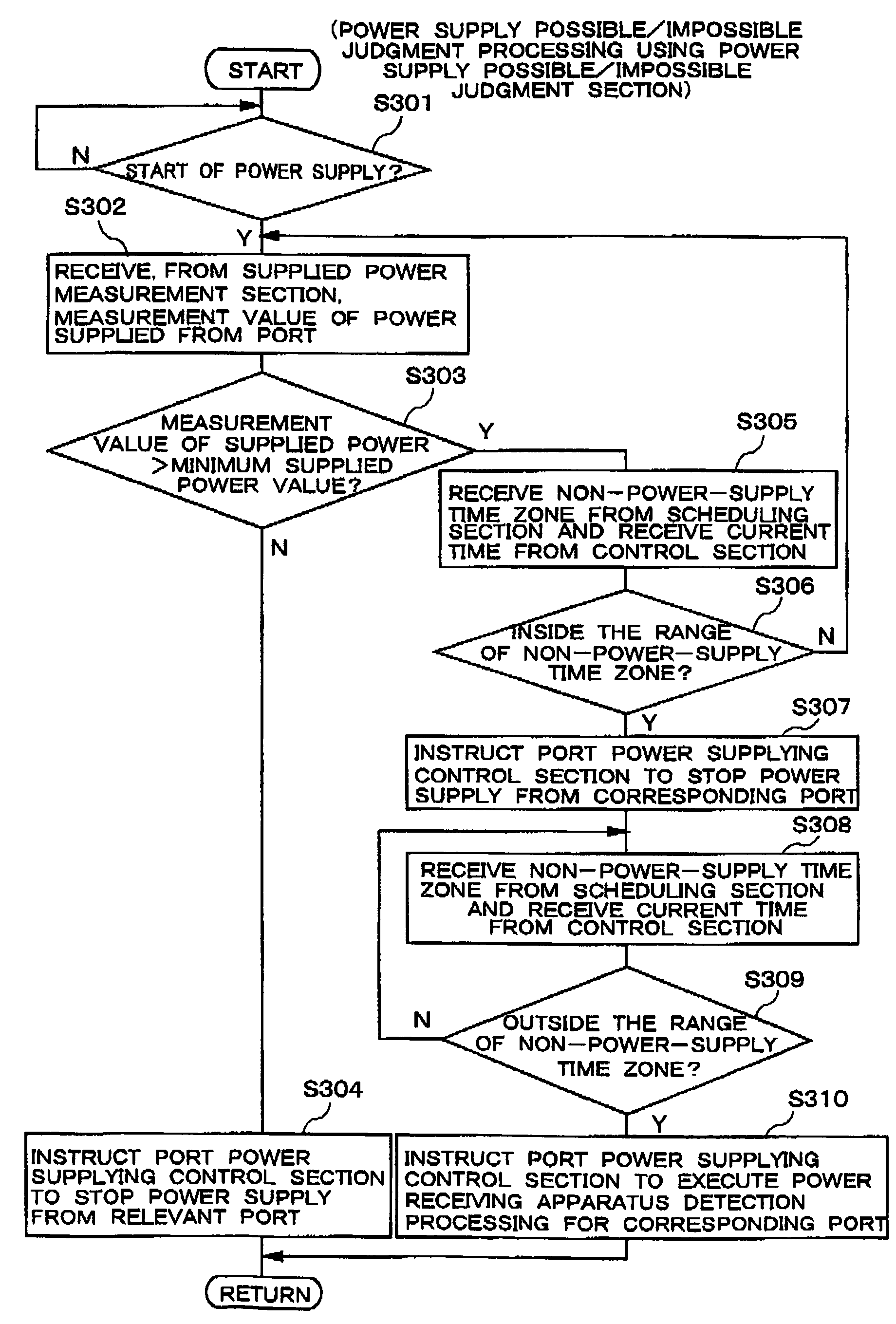
[0021] In the fourth aspect of the present invention, when a communication apparatus to which power is to be supplied is newly connected to one or any one of the a plurality of connectors, each provided with a plurality of connection terminals and part or all of the connection terminals being power supply terminals for supplying power to communication apparatuses to be connected, this connection is detected. Then, power supply using the connector is started for the communication apparatus connected to the corresponding connection terminals. The time data output from the
clock is sequentially compared with the corresponding time zone data in the time zone data indicating non-power-supply time zones each serving as a time zone during which respective power supply terminals should not perform power supply, the time zone being stored in the time zone data storage section in correspondence with each connector. By comparison, the reaching of each non-power-supply time zone is monitored sequentially. When it is judged that any one of the non-power-supply time zones is reached, power supply using the corresponding connector is stopped. Furthermore, the end of each non-power-supply time zone for the connector, power supply to which is stopped is sequentially monitored similarly. When it is judged that the end of the non-power-supply time zone is reached, power supply using the corresponding connector is resumed. Hence, it is possible to prevent power from being supplied to an apparatus to which power is not to be supplied. Furthermore, power supply to the connected communication apparatuses to which power is to be supplied can be started and stopped according to a predetermined schedule, without intermittently supplying power to the communication apparatuses.
Power saving can thus be realized.
[0022] As described above, in the present invention, a judgment is made as to whether a communication terminal connected to a connector, part or all of the connection terminals of which are power supply terminals, is in a state of requiring power supply or not, according to time data and time zone data indicating non-power-supply time zones, or according to the detection of the frequency in which power supply is required and the time threshold value. Then, power supply using the corresponding connector is stopped as necessary. Hence, unnecessary power supply can be reduced, and power saving can be realized. Still further, since this effect is obtained by ingeniously designing only the apparatus on the power
supply side, in the case that there are numerous communication terminals to be connected, the cost of the entire communication
system can be reduced when power saving is realized.

