
User interactive method for indicating a region of interest

a user-interactive and image technology, applied in the field of medical imaging systems, can solve the problem of adding an additional element of complexity to the work with 3d images

Active Publication Date: 2006-03-16
GENERAL ELECTRIC CO
View PDF16 Cites 44 Cited by
  • Summary
  • Abstract
  • Description
  • Claims
  • Application Information

AI Technical Summary

Problems solved by technology

Problems exist with the current methods for selecting the border segments of a ROI.
Still another method has the user draw the contour of the object using a mouse or various keyboard keys, which can be quite time consuming, with accuracy being affected by the display size and resolution, and the minimum distance the user may move the cursor on the display.
Also, working with 3D images adds an additional element of complexity.

Method used


Image

  • User interactive method for indicating a region of interest
  • User interactive method for indicating a region of interest
  • User interactive method for indicating a region of interest

Examples


Embodiment Construction

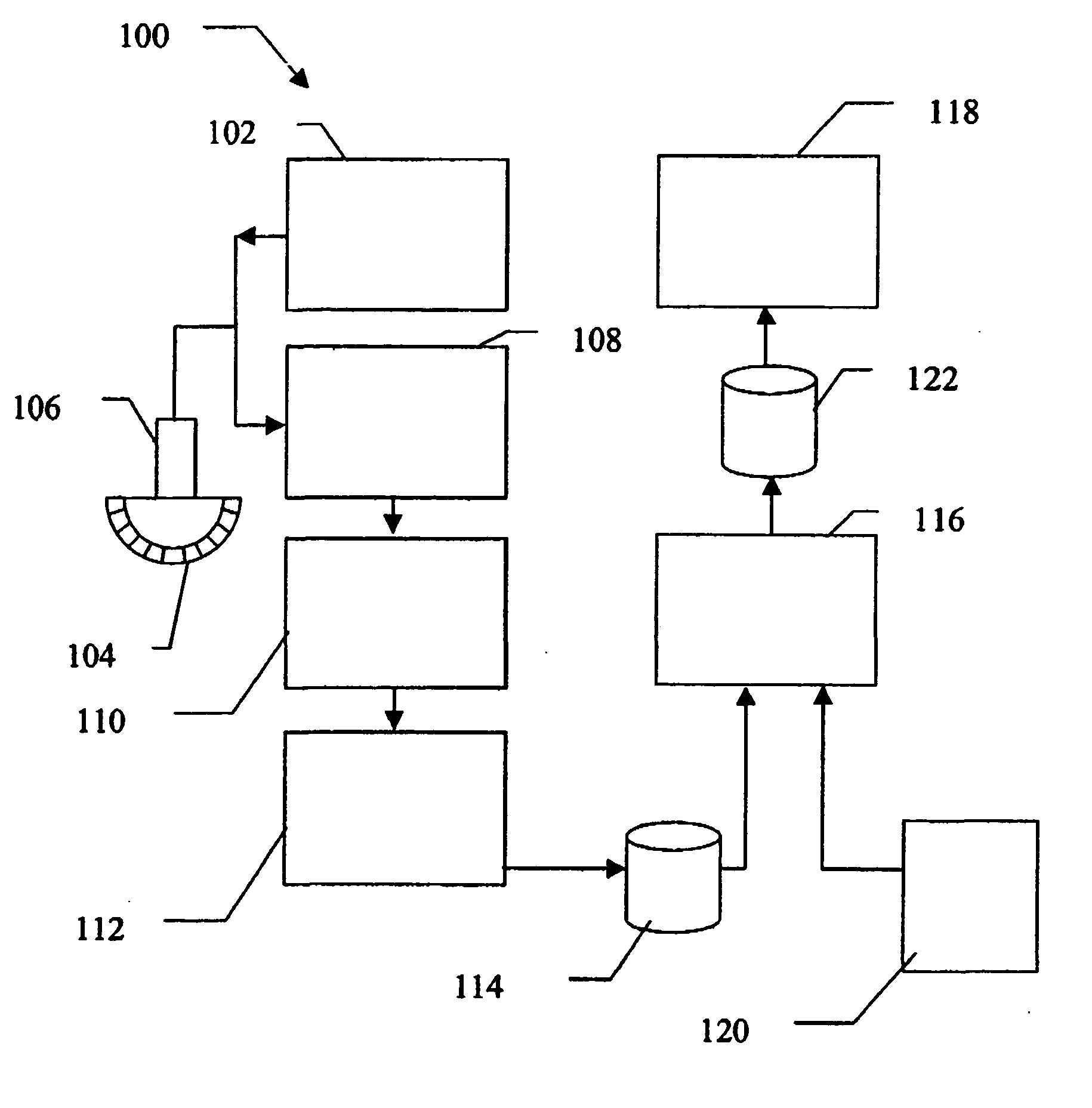
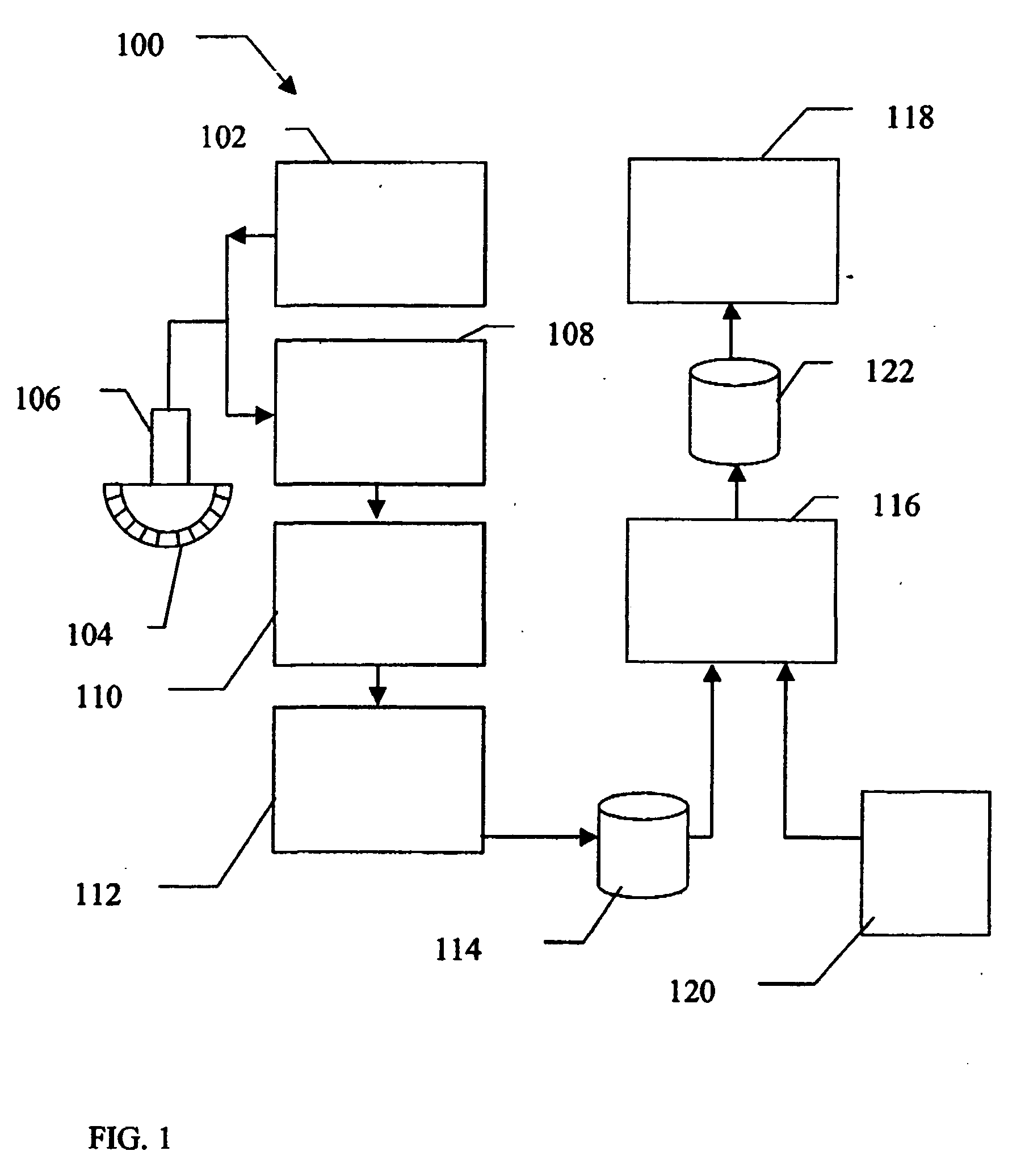
[0015]FIG. 1 illustrates a block diagram of an ultrasound system 100 formed in accordance with an embodiment of the present invention. The ultrasound system 100 includes a transmitter 102 which drives elements 104 within a transducer 106 to emit pulsed ultrasonic signals into a body. A variety of geometries may be used. The ultrasonic signals are back-scattered from structures in the body, like blood cells or muscular tissue, to produce echoes which return to the elements 104. The echoes are received by a receiver 108. The received echoes are passed through a beamformer 110, which performs beamforming and outputs an RF signal. The RF signal then passes through an RF processor 112. Alternatively, the RF processor 112 may include a complex demodulator (not shown) that demodulates the RF signal to form IQ data pairs representative of the echo signals. The RF or IQ signal data may then be routed directly to RF / IQ buffer 114 for temporary storage. A user input 120 may be used to input pa...


PUM


Abstract

Method user interactive indication of a region of interest within an image is provided. A user interface is used to select a point on an initial linear border segment of a region of interest. The user drops the point at a new position and a processor forms a new, non-linear border segment which includes the point.

Description

BACKGROUND OF THE INVENTION [0001] This invention relates generally to medical imaging systems. In particular, the present invention relates to method and apparatus for defining a region of interest in a medical image. [0002] Various methods are available for drawing the contour of an object, within a medical image. For example, the object may be a fetus, organ, cyst, or tumor which the user is interested in further analyzing. The area enclosed by the contour represents the “region of interest” (ROI) of the image. Typically the user is uninterested in the other features shown on the image and selecting a ROI allows the user to concentrate the processor power of the system on the part of the image which is of most interest to the user. [0003] Problems exist with the current methods for selecting the border segments of a ROI. For example, one method is to employ known shapes, such as rectangles, circles and ovals, then require the user to drag the contour of the shape to the desired l...

Claims


Application Information

Patent Timeline
Patent Type & Authority Applications(United States)
IPC IPC(8): A61B5/05
CPCA61B8/00A61B8/0866A61B8/463G01S7/52074A61B8/469A61B8/483A61B8/465
Inventor DEISCHINGER, HARALDHOBELSBERGER, PETRADUDA, WALTER
Owner GENERAL ELECTRIC CO
Learn More