Ultrasonographic device

a technology of ultrasonography and diagnostic equipment, applied in the field of ultrasonography diagnostic equipment, can solve problems such as patterns, and achieve the effect of reducing image distortion and ensuring image quality

Inactive Publication Date: 2006-03-16
PANASONIC CORP
View PDF8 Cites 0 Cited by
  • Summary
  • Abstract
  • Description
  • Claims
  • Application Information

AI Technical Summary

Benefits of technology

[0028] According to this feature, also when three-dimensional scanning is performed using the two-dimensional array element, the control of the received beam propagation is performed, thereby enabling the shapes of the composite beams to be close to straight lines.
[0029] According to the present invention, an ultrasonic diagnostic equipment which can prevent the stripe patterns in the display image from being generated and obtain a preferable image quality with reduced image distortion even when performing parallel reception, can be provided.

Problems solved by technology

Therefore, a first composite beam of the transmitted beam and the first received beam and a second composite beam of the transmitted beam and the second received beam deflect toward the transmitted beam side in the vicinity of the focus of the transmitted beam and deflect toward the first and the second received beam sides, respectively, in the shallower area and the deeper area than the focus as shown by the dotted lines in FIG. 7B and thereby there is a problem that the first and the second composite beams are not made parallel to each other and when the image is displayed, stripe patterns occur in the display image.

Method used


Image

  • Ultrasonographic device
  • Ultrasonographic device
  • Ultrasonographic device

Examples


embodiment 1

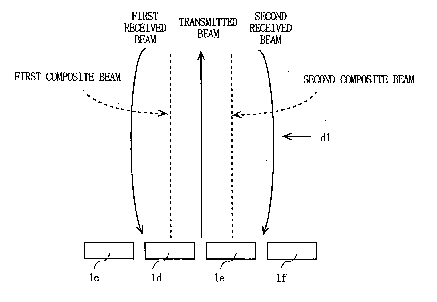
[0063]FIG. 1 is a diagram illustrating shapes of transmitted and received beams and a positional relationship among them in the ultrasonic diagnostic equipment performing parallel reception through linear scanning using the array element according to a first embodiment of the present invention.

[0064] In FIG. 1, in a case where a transmitted beam propagates from the intermediate position between the elements 1d and 1e, a first received beam propagates to the intermediate position between the elements 1c and 1d, and a second received beam propagates to the intermediate position between the elements 1e and 1f, it is desired that a first composite beam is disposed at the position of the element 1d and a second composite beam is disposed at the position of the element 1e. At this time, in order to prevent the first and the second composite beams from deflecting toward the transmitted beam side in the vicinity of the transmission focus depth, the directivities of the first and the second...

embodiment 2

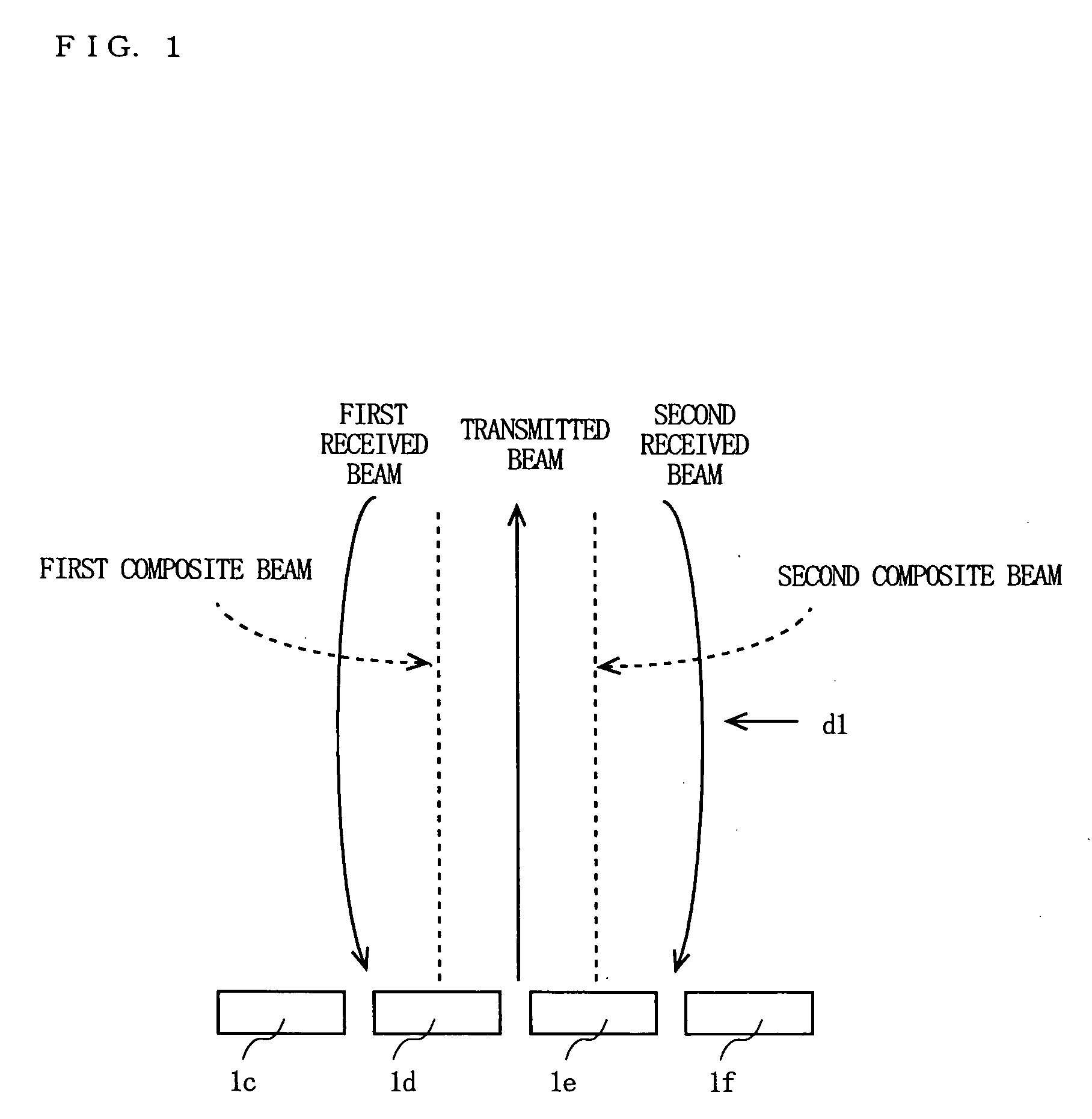
[0066]FIG. 2 is a diagram illustrating shapes of the transmitted and received beams and a positional relationship among them in the ultrasonic diagnostic equipment performing parallel reception through linear scanning using the array element according to a second embodiment of the present invention.

[0067] In FIG. 2, in a case where the transmitted beam propagates from the intermediate position between the elements 1d and 1e, the first received beam propagates to the intermediate position between the elements 1c and 1d, and the second received beam propagates to the intermediate position between the elements 1e and 1f, it is desired that the first composite beam is disposed at the position of the element 1d and the second composite beam is disposed at the position of the element 1e. At this time, in order to prevent the first and the second composite beams from deflecting toward the transmitted beam side in the vicinity of the transmission focus depth, the directivities of the first...

embodiment 3

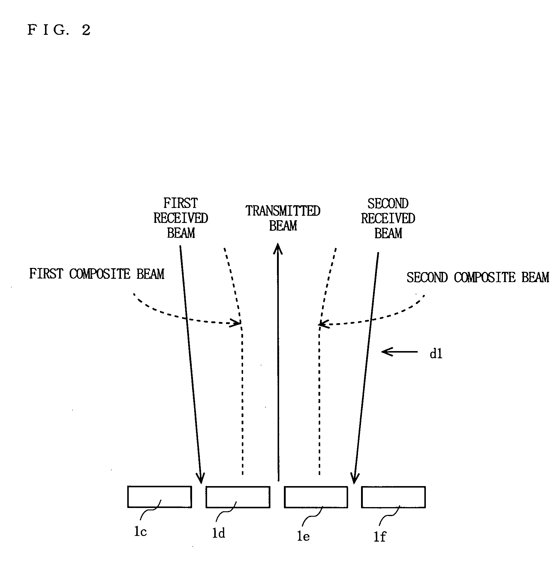
[0070]FIG. 3 is a diagram for explaining and schematically showing that the reception focus positions are controlled by controlling gains of the receiving circuit in the ultrasonic diagnostic equipment performing parallel reception through linear scanning using the array element according to a third embodiment of the present invention. In FIG. 3, only the transmitted beam and the first received beam are illustrated and the second received beam is omitted.

[0071] In FIG. 3, thick lines A1, A2, and A3 drawn above the elements 1a to 1f indicate gains of the receiving circuit, which correspond to the respective elements, that is, weighting. For example, as to the thick line A1, the thick line part corresponding to the position of the element 1c is positioned higher in the figure than the thick line part corresponding to the position of the element 1a, which indicates that the element 1c has a higher gain of the receiving circuit than the element 1a. Further, A1, A2, and A3 are indicated...


PUM


Abstract

According to the present invention, provided is an ultrasonic diagnostic equipment which meanders the reception focus position so that the reception focus position is made further away from the transmitted beam at the transmission focus depth d1 and is made closer to the transmitted beam in areas shallower and deeper than the depth d1, and thereby makes the shapes of the first and the second composite beams straight lines, thereby preventing the stripe patterns in the display image from being generated and enabling a preferable image quality with reduced image distortion to be obtained, even when the parallel reception is performed.

Description

TECHNICAL FIELD [0001] The present invention relates to an ultrasonic diagnostic equipment which performs transmission and reception using an array element to obtain information on a body to be examined. BACKGROUND ART [0002] A principle of an ultrasonic diagnostic equipment which repeatedly performs transmissions into and receptions from, of ultrasonic waves, a body to be examined using an array element, thereby to obtain the body information to be examined as a two-dimensional image, is already known. [0003] A tomographic image which is formed by scanning the two-dimensional surface using the ultrasonic beam is called a frame, and an index indicating how many cross-sections of the frames can be displayed for one second is called a frame rate. For example, a frame rate of 15 frame / s means that 15 cross-sections of tomographic images can be obtained for one second. It is known that an image is seen flickering at a frame rate smaller than 30 frame / s, based on characteristics of the h...

Claims


Application Information

Patent Timeline
Patent Type & Authority Applications(United States)
IPC IPC(8): A61B8/06G01S7/52
CPCG01S7/52046A61B8/00
Inventor NISHIGAKI, MORIO
Owner PANASONIC CORP
Why Eureka
Try Eureka