Optical unit and method for determining reflection plane

Active Publication Date: 2022-03-22
KOITO MFG CO LTD
View PDF19 Cites 0 Cited by
  • Summary
  • Abstract
  • Description
  • Claims
  • Application Information

AI Technical Summary

Benefits of technology

[0014](4) Also, it is yet another exemplary purpose of the present invention to provide a technique for suppressing glare that occurs due to the

Problems solved by technology

Accordingly, such an arrangement has the potential to cause a situation in which a light source image cannot be clearly projected depending on the direction in which the light emitted from the light source is reflected by the blade.
(2) The above-described apparatus has the potential to cause a situation in which the light distribution pattern cannot be formed in a rectangular shape depending on the position relation between the rotating reflector, the light source, and the projector lens.
(4) The above-described appar

Method used


Image

  • Optical unit and method for determining reflection plane
  • Optical unit and method for determining reflection plane
  • Optical unit and method for determining reflection plane

Examples


embodiments

[0067]Description will be made below regarding the present invention based on preferred embodiments with reference to the drawings. The same or similar components, members, and processes are denoted by the same reference numerals, and redundant description thereof will be omitted as appropriate. The embodiments have been described for exemplary purposes only, and are by no means intended to restrict the present invention. Also, it is not necessarily essential for the present invention that all the features or a combination thereof be provided as described in the embodiments.

[0068]An optical unit including a rotating reflector according to the present embodiment is applicable to various kinds of automotive lamps. First, description will be made regarding the schematic configuration of an automotive headlamp system that is capable of mounting an optical unit according to the embodiment described later.

(Automotive Headlamp)

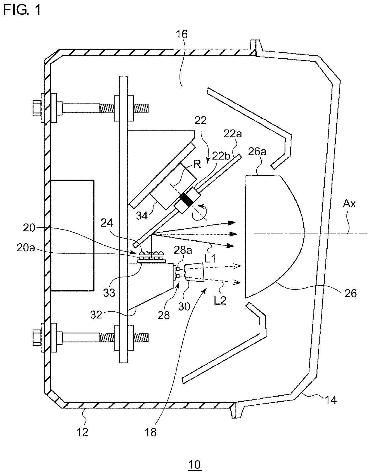
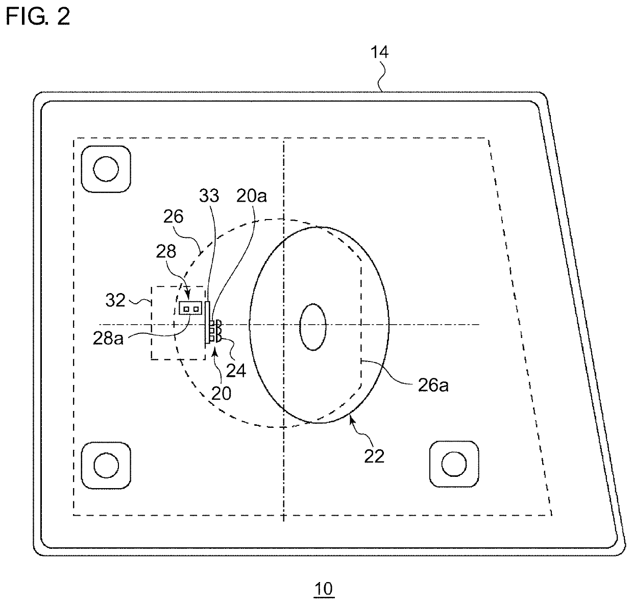
[0069]FIG. 1 is a horizontal cross-sectional schematic diagram ...

second embodiment

[0106]Next, description will be made regarding the formation of a light distribution pattern by means of an optical unit including a rotating reflector according to the present embodiment. FIG. 9A is a side view showing a schematic configuration of the optical unit according to a reference example. FIG. 9B is a schematic diagram for explaining a light distribution pattern formed by the optical unit according to the reference example.

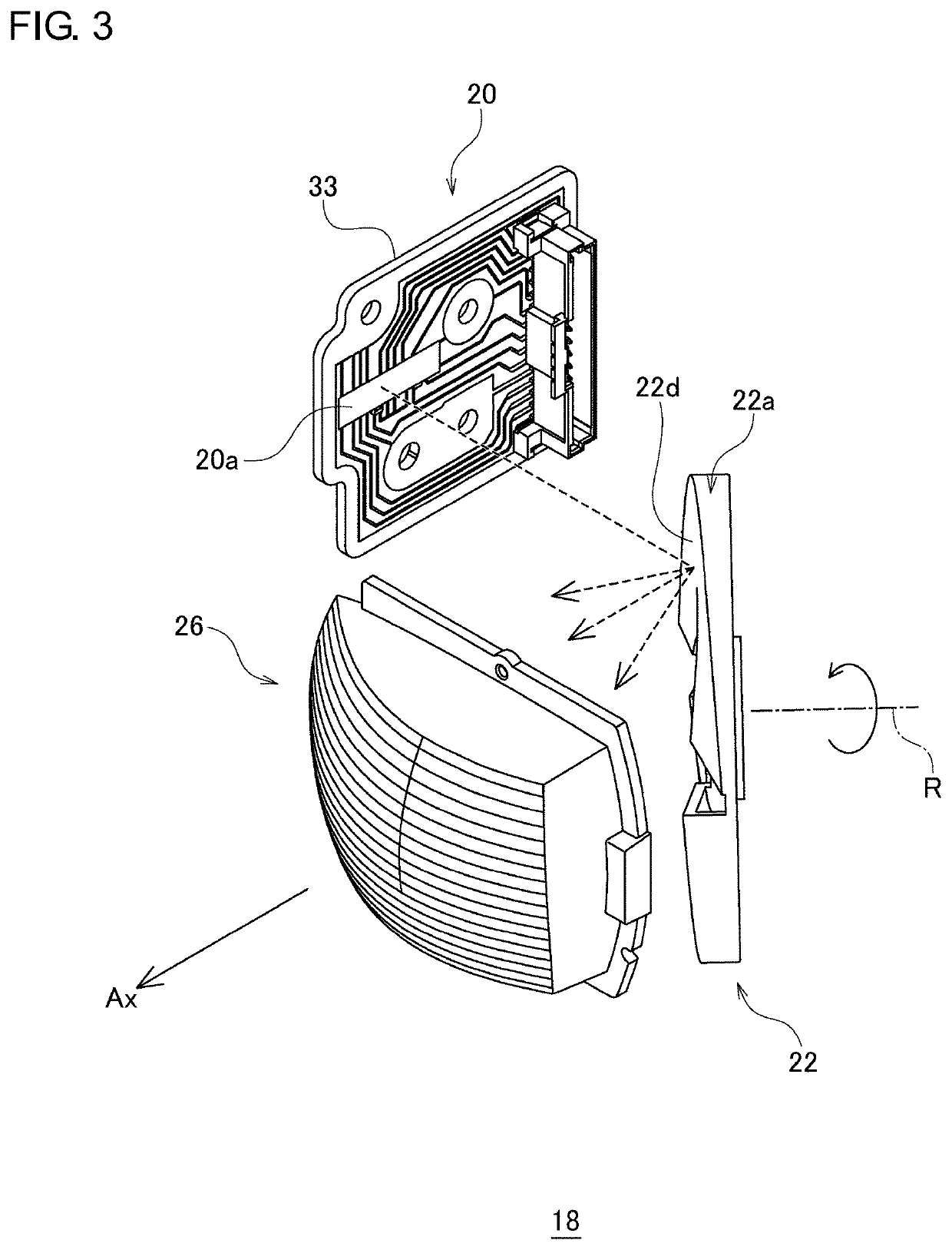
[0107]An optical unit 39 according to the reference example includes a first light source 20 including a light-emitting element such as an LED or the like, a rotating reflector 22 configured to be rotated in a single direction with its rotational axis as the center of rotation while reflecting the light emitted from the first light source 20, and a convex lens 26 configured to project the light reflected by the rotating reflector 22 in the light irradiation direction. The rotating reflector 22 is provided with a reflective face 22d around the rotational ...

third embodiment

(Method for Determining Reflective Face of Rotating Reflector)

[0123]FIG. 13 is a schematic diagram for explaining a method for determining the reflective face supported by the optical unit according to the present embodiment. FIG. 14 is a diagram showing a flowchart for the reflective face determining method according to the present embodiment. The reflective face determining method according to the present embodiment is a method for determining the reflective face 22d of the rotating reflector 22 configured to be rotated in a single direction with the rotational axis R as the center of rotation while reflecting the light emitted from the first light source 20.

[0124]First, a desired light distribution pattern PH to be formed on the front side is set (S10 in FIG. 14). Furthermore, an optical face such as an input face and an output face of the projector lens (convex lens 26) are set so as to provide the light distribution pattern PH (Step S12 in FIG. 14). Next, a region VR of a virtu...


PUM


Abstract

An optical unit includes: a light source; a rotating reflector configured to be rotated in a single direction with the rotational axis as the center of rotation while reflecting light emitted from the light source; and a projector lens configured to project light reflected by the rotating reflector in the light irradiation direction. The projector lens has a first lens region LR1 that defines the first focal plane and a second lens region that defines the second focal plane that differs from the first focal plane. The light source is arranged such that, when the rotating reflector is set to the first rotational position, its virtual position is in the vicinity of the focal plane, and such that, when the rotating reflector is set to the second rotational position, its virtual position is in the vicinity of the focal plane.

Description

BACKGROUND1. Technical Field[0001]The present invention relates to an optical unit that is applicable to a lamp such as an automotive lamp or the like. Also, the present invention relates to a method for determining a reflective face of a rotating reflector or the like.2. Description of the Related Art[0002](1) (2) In recent years, an apparatus has been proposed configured to reflect light emitted from a light source toward an area in front of a vehicle, and to scan the area in front of the vehicle using the reflected light thereof, so as to form a predetermined light distribution pattern. For example, such an apparatus includes a rotating reflector configured to rotate in a single direction with its rotational axis as the center of rotation while reflecting the light emitted from the light source, and a light source configured as a light-emitting element. The rotating reflector is provided with a reflective face such that the light emitted from the light source is reflected by the ...

Claims


Application Information

Patent Timeline
IPC IPC(8): F21S41/675F21S41/33F21S41/25F21S41/37F21S41/148
CPCF21S41/675F21S41/148F21S41/25F21S41/33F21S41/37F21S41/153F21S41/275
Inventor TANAKA, HIDETADASAKURAI, KAZUTOSHI
Owner KOITO MFG CO LTD
Why Eureka
Try Eureka