LED luminaire and a modular luminaire system

a technology of led luminaires and modules, applied in the field of led luminaires, can solve the problems of large lens and housing, large luminaires, and large led boards, and achieve the effects of low cost, constant cross sectional shape, and strength and rigidity

Inactive Publication Date: 2021-02-04
SIGNIFY HLDG BV
View PDF0 Cites 0 Cited by
  • Summary
  • Abstract
  • Description
  • Claims
  • Application Information

AI Technical Summary

Benefits of technology

[0019]This arrangement provides a modular luminaire design in which the LED arrangements are formed on a frame-type structure formed of straight (hence low cost) sections, with electrical and mechanical connections between those sections made by a connecting section. The frame structure together with the driver unit forms a closed shape, giving strength and rigidity. The frame provides an open structure which assists in cooling. The support arms function both as heat sinks and as support structures. The frame design means less material needs to be used to achieve the required cooling, as well as enabling a modular design.
[0020]The first and second support arms for example have constant cross sectional shape along their length. This means they can be produced at low cost. The same manufacturing equipment may also be used to form support arms of different length.
[0021]The first and second support arms are for example formed of extruded metal. This provides a particularly low cost solution, for example compared to conventional die casting. The first and second support arms may be formed of extruded aluminum.

Problems solved by technology

To match each LED chip with one lens, the LEDs must be placed sparsely which makes the LED board very big.
Consequently, the lens and housing are large, which has cost implications as well as making the luminaire large and heavy.
If the lens is fabricated by injection molding, a large required size results in more difficult and expensive manufacture.
There is also a problem that different luminaire requirements, such as lighting power, require different sizes of the luminaire, with different die casting and injection molding tooling.
However, this structure is expensive to manufacture and it is difficult to scale the design to different requirements.

Method used


Image

  • LED luminaire and a modular luminaire system
  • LED luminaire and a modular luminaire system
  • LED luminaire and a modular luminaire system

Examples


Embodiment Construction

[0049]The invention will be described with reference to the Figures.

[0050]It should be understood that the detailed description and specific examples, while indicating exemplary embodiments of the apparatus, systems and methods, are intended for purposes of illustration only and are not intended to limit the scope of the invention. These and other features, aspects, and advantages of the apparatus, systems and methods of the present invention will become better understood from the following description, appended claims, and accompanying drawings. It should be understood that the Figures are merely schematic and are not drawn to scale. It should also be understood that the same reference numerals are used throughout the Figures to indicate the same or similar parts.

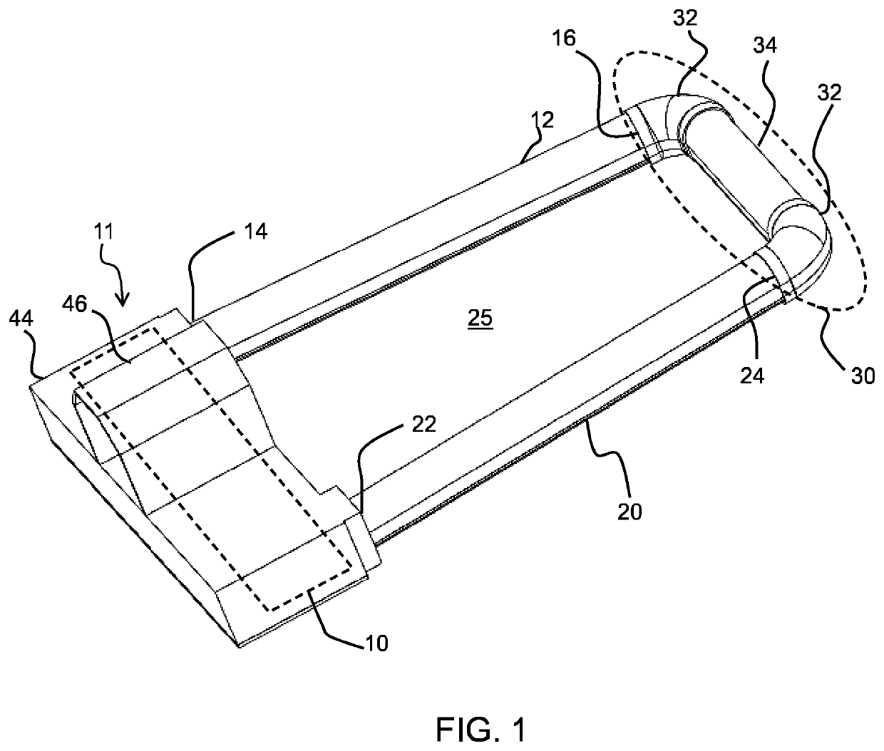
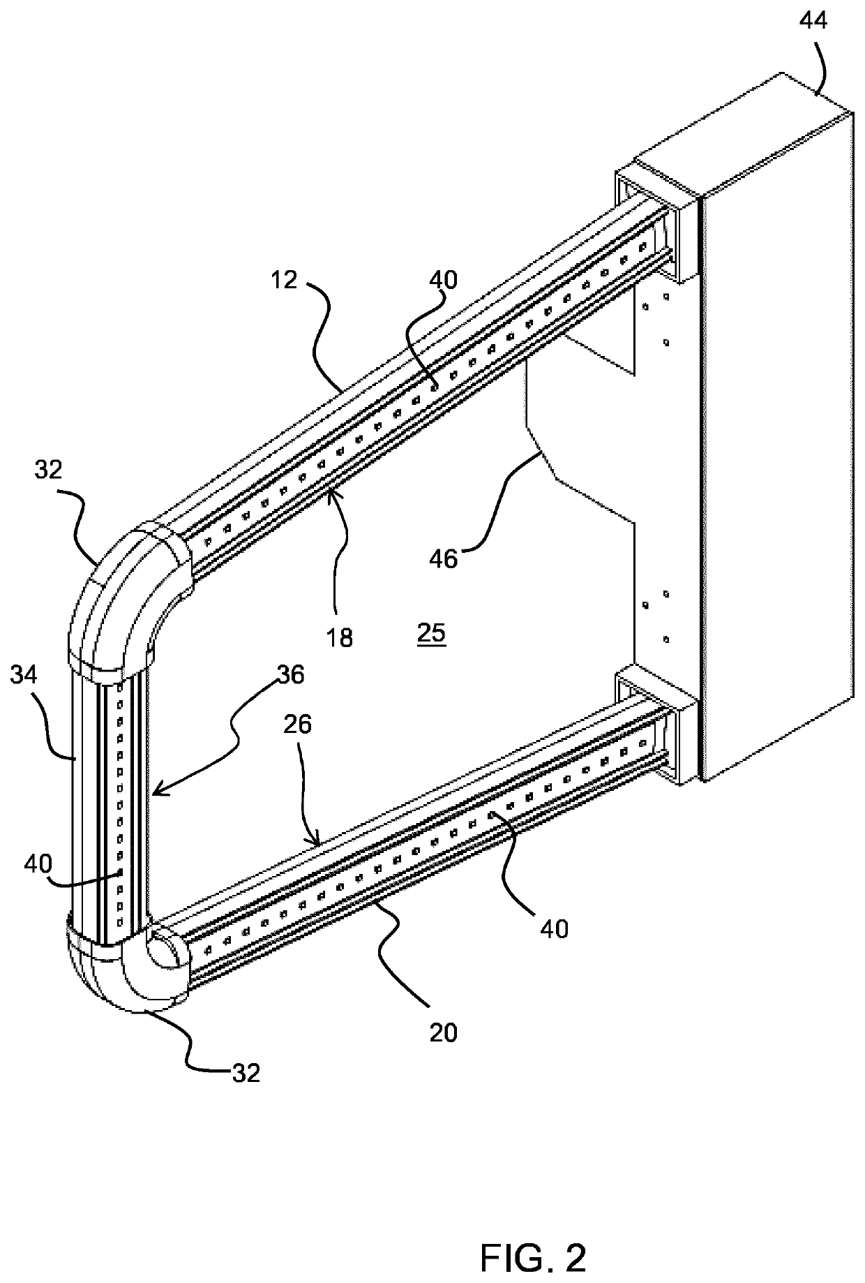
[0051]The invention provides a LED luminaire comprising a frame shape formed of straight arms which each carries an LED arrangement, and connections which provide mechanical connection between the support arms and electric...


PUM


Abstract

The invention provides a LED luminaire comprising a frame shape formed of straight arms (12, 20) which each carry an LED arrangement (18, 26), and connections (30) which provide mechanical connection between the support arms (12, 20) and electrical connection between the LED arrangements (18, 26) of those arms (12, 20). The frame shape has a central opening (25) which assists cooling by convection and it can be manufactured using a low cost extrusion process.

Description

FIELD OF THE INVENTION[0001]This invention relates to LED luminaires.BACKGROUND OF THE INVENTION[0002]LED luminaires are increasingly replacing conventional luminaires, such as based on fluorescent lighting. One example is road lighting luminaires.[0003]Normally, LED road lighting luminaires make use of a large and heavy die cast housing. The purpose is to provide sufficient heat dissipation capability as well as a certain strength to protect the luminaire from impact.[0004]The light distribution from a road luminaire must match strict conditions, which mean that an optical lens is also required. For example, a typical LED road lighting luminaire uses a so-called “peanut lens” (which is a dome shaped lens with a central waist) over each LED chip to realize the required light distribution.[0005]To match each LED chip with one lens, the LEDs must be placed sparsely which makes the LED board very big. Consequently, the lens and housing are large, which has cost implications as well as ...

Claims


Application Information

Patent Timeline
Patent Type & Authority Applications(United States)
IPC IPC(8): F21S8/08F21V15/01F21V15/015
CPCF21S8/086F21Y2103/37F21V15/015F21V15/013F21V19/02F21W2131/103F21Y2115/10
Inventor CHEN, MINSUI, LEILI, QINZHOU, LEONLUO, LINDA
Owner SIGNIFY HLDG BV
Why Eureka
Try Eureka