Tool and method for direct squeeze casting

a direct squeeze and casting technology, applied in the field of direct squeeze casting tools and methods, can solve the problems of limited volume and prototype cast parts, high tooling costs for permanent mold processes, and designers relying on low volume sand cast parts, so as to improve heat transfer characteristics of casting, improve management, and improve thermal properties

Inactive Publication Date: 2018-12-06
GM GLOBAL TECH OPERATIONS LLC
View PDF8 Cites 0 Cited by
  • Summary
  • Abstract
  • Description
  • Claims
  • Application Information

AI Technical Summary

Benefits of technology

[0017]In this manner, the contoured shape of the internal passage improves the management of heat transfer, the venting, and the movement of molten metal into the mold during the casting and solidification process. In particular, the contouring of the internal passage ensures that the internal passages more closely approach an optimized shape that better fits with the shape of the casting and provides improved heat transfer characteristics for the casting. As a result, materials having better thermal properties may be used for the mold tool and the properties of those mold tools may be improved. This improves the solidification pattern of the castings, reduces cycle times, reduces the cost of the mold tool, reduces the time required to produce the mold tool, and reduces the cost of the overall mold system.
[0018]Further, the contoured shape of the internal passages reduce or eliminate the presence of stress risers or concentrators in comparison to the conventional passage, thereby improving resistance to thermal fatigue and tool life. The contoured shape of the internal passage also may improve the flow of molten metal through the tool. Additionally, the improved surface of the contoured internal passages may provide a micro-rough surface which increases the thermal transfer capacity between the die / tool and the molten metal.
[0019]The advantages provided by these exemplary embodiments enable the use of a coring technique that more closely shapes the internal passages to an optimized shape. The shape, volume, size and surface texture of the contoured internal passages may be optimized to provide enhanced thermal transfer characteristics in those regions where high heat flux or heat extraction is desired. In comparison to conventional machined tools, the contoured internal passages in the exemplary embodiments may also result in a more compact and lighter tool. These and other advantages will become evident from the following detailed description.

Problems solved by technology

Low volume and prototype cast parts are generally limited to sand cast processes because the tooling costs for permanent mold processes may be prohibitive.
The part designers who rely upon these low volume sand cast parts are faced with a significant problem: the characteristics of sand cast parts may not generally exhibit the same characteristics as those which are created using high volume permanent mold processes.
This places a significant limitation on the ability of a part designer to verify a design early in the design process.
Although the tools used for a HPDC process are more expensive and require a much longer lead time to produce, these costs may be distributed over the large number of parts that are generated by the HPDC process so that the individual part cost may be lower.
However, the HPDC process also has some problems.
Typically, as molten metal is introduced into a mold, the HPDC high velocity fill processes entrain air, generate oxides, and have difficulty addressing metal shrinkage from certain regions within the mold.
Current tool fabrication techniques severely limit the shape of the internal passages.
Therefore, these machined internal passages are limited to only having a straight shape.
This further severely limits the route that the resultant machined internal passage may take through the mold tool.
The fact that these passages are limited to only having a straight shape that originates from an external surface, as a result of the fact that they are machined, severely limits the capability of the mold tool designer to design internal passages which may better manage the solidification conditions and solidification pattern of the casting.
In order to machine these passages, the tool must be relatively thick and heavy.
Additionally, any passages which result from the machining include sharp edges at the intersections which act as stress raisers or concentrators which reduce the resistance to thermal fatigue.

Method used


Image

  • Tool and method for direct squeeze casting
  • Tool and method for direct squeeze casting
  • Tool and method for direct squeeze casting

Examples


Embodiment Construction

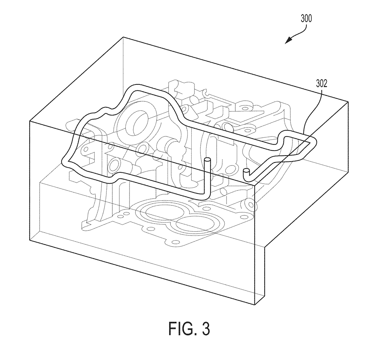
[0028]FIG. 3 is an interior view of an exemplary top mold tool 300 for a direct squeeze casting (DSC) system. The top mold tool 300 includes a curved internal passage 302. Unlike internal passages in conventional direct squeeze mold tools which are limited by machining methods to only including straight shaped sections, the internal passage 302 includes multiple curved sections. As is clearly illustrated, the internal passage 302 is quite complex and its shape has been optimized for the specific mold design to provide the highest quality molded part. In an exemplary embodiment, the complex and optimized internal passage is provided by forming the top mold tool 300 using a casting process which relies upon the use of a core to form the internal passage. A core is a device used in casting processes to provide internal passages having shapes and locations within the mold tool which may otherwise not be achieved through other methods, such as by a machining process.

[0029]FIG. 4 is a cro...


PUM

PropertyMeasurementUnit
ductileaaaaaaaaaa
pressureaaaaaaaaaa
pressure sensitiveaaaaaaaaaa

Abstract

A casting tool for a direct squeeze casting process that includes a cast mold tool with a contoured internal passage for better die thermal management. This enables the use of a grey cast iron mold material. A durable mold surface may also be formed through a nodular cast iron reaction with a Magnesium addition in either sand core or sand core coating.

Description

INTRODUCTION[0001]This introduction generally presents the context of the disclosure. Work of the presently named inventors, to the extent it is described in this introduction, as well as aspects of the description that may not otherwise qualify as prior art at the time of filing, are neither expressly nor impliedly admitted as prior art against this disclosure.[0002]Low volume and prototype cast parts are generally limited to sand cast processes because the tooling costs for permanent mold processes may be prohibitive. The part designers who rely upon these low volume sand cast parts are faced with a significant problem: the characteristics of sand cast parts may not generally exhibit the same characteristics as those which are created using high volume permanent mold processes. This places a significant limitation on the ability of a part designer to verify a design early in the design process.[0003]Current high volume manufacturing processes for producing engine components of a m...

Claims


Application Information

Patent Timeline
Patent Type & Authority Applications(United States)
IPC IPC(8): B22D18/02
CPCB22D18/02
Inventor OSBORNE, RICHARDWANG, QIGUIDOTY, HERBERT W.
Owner GM GLOBAL TECH OPERATIONS LLC
Why Eureka
Try Eureka