Vertrebal body placeholder

a placeholder and vertebral body technology, applied in the field of vertebral body spacers, can solve problems such as high surface pressur

Inactive Publication Date: 2006-03-16
METZ STAVENHAGEN PETER
View PDF8 Cites 103 Cited by
  • Summary
  • Abstract
  • Description
  • Claims
  • Application Information

AI Technical Summary

Benefits of technology

[0013] In a particularly preferred embodiment, at least one spike is mounted on the cover. In this case, it has been found advantageous to mount four equidistant spikes thereon. With said spikes, the cover penetrates the neighbouring vertebral bone and prevents the vertebral body spacer from coming out of place.

Problems solved by technology

In cancellous bones, it may happen that the upper edge of the vertebral body spacer in accordance with DE 202 07 853.1 is pressed into the bone since the contact surface between the vertebral body spacer and the neighbouring vertebral bone is comparably small, resulting in a high surface pressure.

Method used


Image

  • Vertrebal body placeholder
  • Vertrebal body placeholder
  • Vertrebal body placeholder

Examples


Embodiment Construction

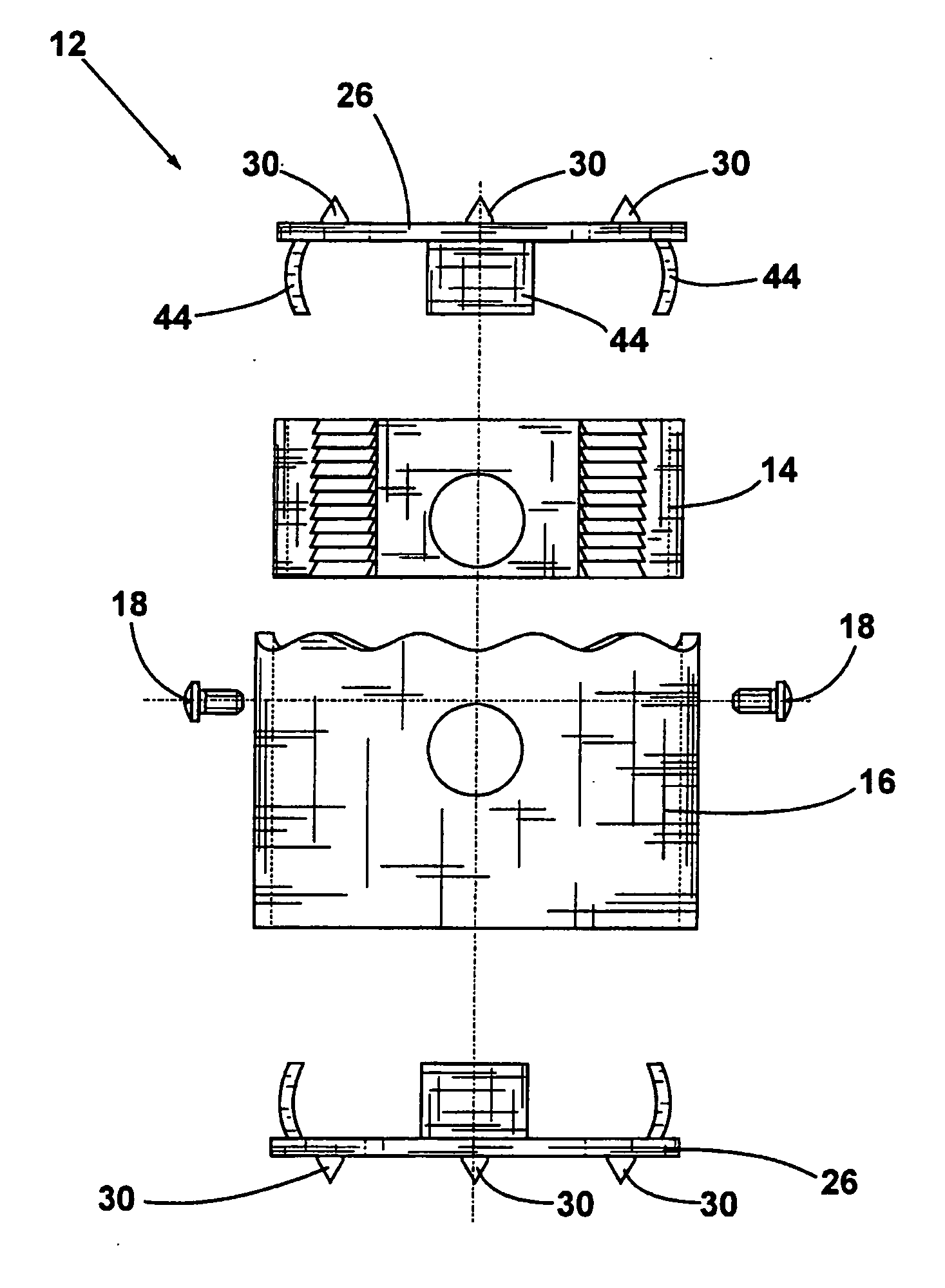
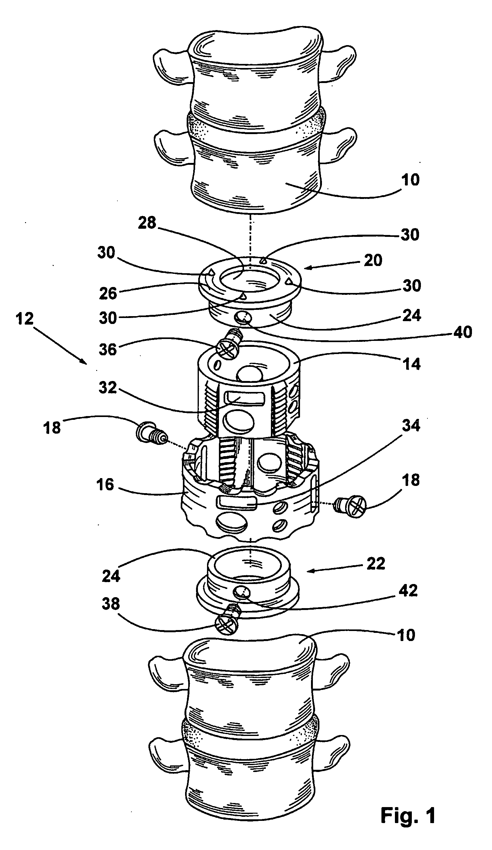
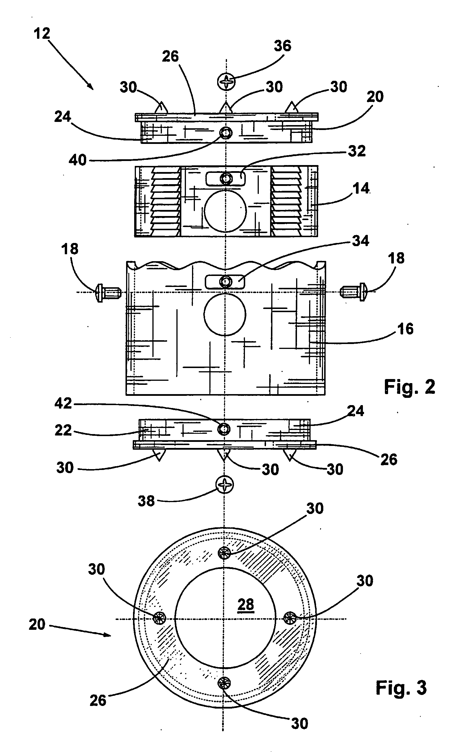
[0022] The spine 10 illustrated in the FIGS. 1 through 3 includes various vertebral bodies 10 and a bipartite, cylindrical hollow vertebral body spacer 12 that is mounted between two neighbouring vertebral bodies 10. Said vertebral body spacer 12 is comprised of a smaller, cylindrical inner body 14 and of a larger, sleeve-like outer body 16 which is also cylindrical and positively and telescopically receives the inner body 14. In an effort to achieve an optimal position of the spine, the operating surgeon may fix inner body 14 and outer body 16 in the desired relative position using two fixation screws 18. A long hole 34 arranged in the outer body 16 permits to fix the vertebral body spacer 12 in any position. Above the inner body 14 and beneath the outer body 16 there is provided one cover 20, 22 respectively, said covers being provided with a cylindrical guide means 24 and with an annular cover wall 26 that is disposed perpendicularly to the guide means 24.

[0023] In the cover wal...


PUM


Abstract

The invention relates to a vertebral body placeholder comprising a cylindrical inner body (14), which can be inserted in a telescopic manner into a coaxially arranged, sleeve-shaped outer body (16). The aim of the invention is to create a vertebral body placeholder that does not unwantedly penetrate spongy vertebrae. To this end, a cap (20, 22) is placed on a face of the inner body (14) and/or on a face of the outer body (16).

Description

CROSS-REFERENCE TO RELATED APPLICATIONS [0001] This application claims Priority from German Application No. DE 202 13 013.4 filed on 24. Aug. 2002 BACKGROUND OF THE INVENTION [0002] 1. Field of the Invention [0003] The present invention relates to a vertebral body spacer having a cylindrical inner body that is telescopically slidable into a coaxially arranged, sleeve-shaped outer body. [0004] 2. Description of the Prior Art [0005] Such a vertebral body spacer is known from DE 202 07 853.1 for example. In cancellous bones, it may happen that the upper edge of the vertebral body spacer in accordance with DE 202 07 853.1 is pressed into the bone since the contact surface between the vertebral body spacer and the neighbouring vertebral bone is comparably small, resulting in a high surface pressure. BRIEF SUMMARY OF THE INVENTION [0006] In view thereof, it is the object of the present invention to provide a vertebral body spacer that does not incidentally penetrate in bones, even if canc...

Claims


Application Information

Patent Timeline
Patent Type & Authority Applications(United States)
IPC IPC(8): A61F2/44A61F2/00A61F2/30
CPCA61F2/30744A61F2230/0069A61F2002/30115A61F2002/30235A61F2002/3024A61F2002/30367A61F2002/30373A61F2002/30433A61F2002/30489A61F2002/30507A61F2002/3054A61F2002/3055A61F2002/30551A61F2002/30571A61F2002/30601A61F2002/30774A61F2002/30777A61F2002/30785A61F2002/30787A61F2002/30841A61F2002/4475A61F2220/0025A61F2220/0033A61F2220/0041A61F2230/0006A61F2/44A61F2002/30487A61F2002/30593
Inventor METZ-STAVENHAGEN, PETER
Owner METZ STAVENHAGEN PETER
Why Eureka
Try Eureka