Sensor mat

a technology of sensors and mats, applied in the field of sensors, can solve the problems of almost impossible slipping out of place, and achieve the effect of reducing expenditure and improving reliability

Inactive Publication Date: 2006-06-29
ROBERT BOSCH GMBH
View PDF9 Cites 6 Cited by
  • Summary
  • Abstract
  • Description
  • Claims
  • Application Information

AI Technical Summary

Benefits of technology

[0006] Slipping out of place of the sensor mat / functional mat during the construction of the seat cushion is effectively avoided.
[0007] The fixing aid is achieved by the suitable geometrical design of the sensor mat and the devices already present in the seat cushion for fixing on the seat cover (such as wing clips). This clearly reduces the expenditure and, at the same time, gains in reliability, since slipping out of place becomes almost impossible. The appropriately designed sensor mat is snapped into the present device for fixing on the seat cover (e.g. wing clips) and is thereby positioned into the setpoint position.

Problems solved by technology

This clearly reduces the expenditure and, at the same time, gains in reliability, since slipping out of place becomes almost impossible.

Method used


Image

  • Sensor mat
  • Sensor mat
  • Sensor mat

Examples


Embodiment Construction

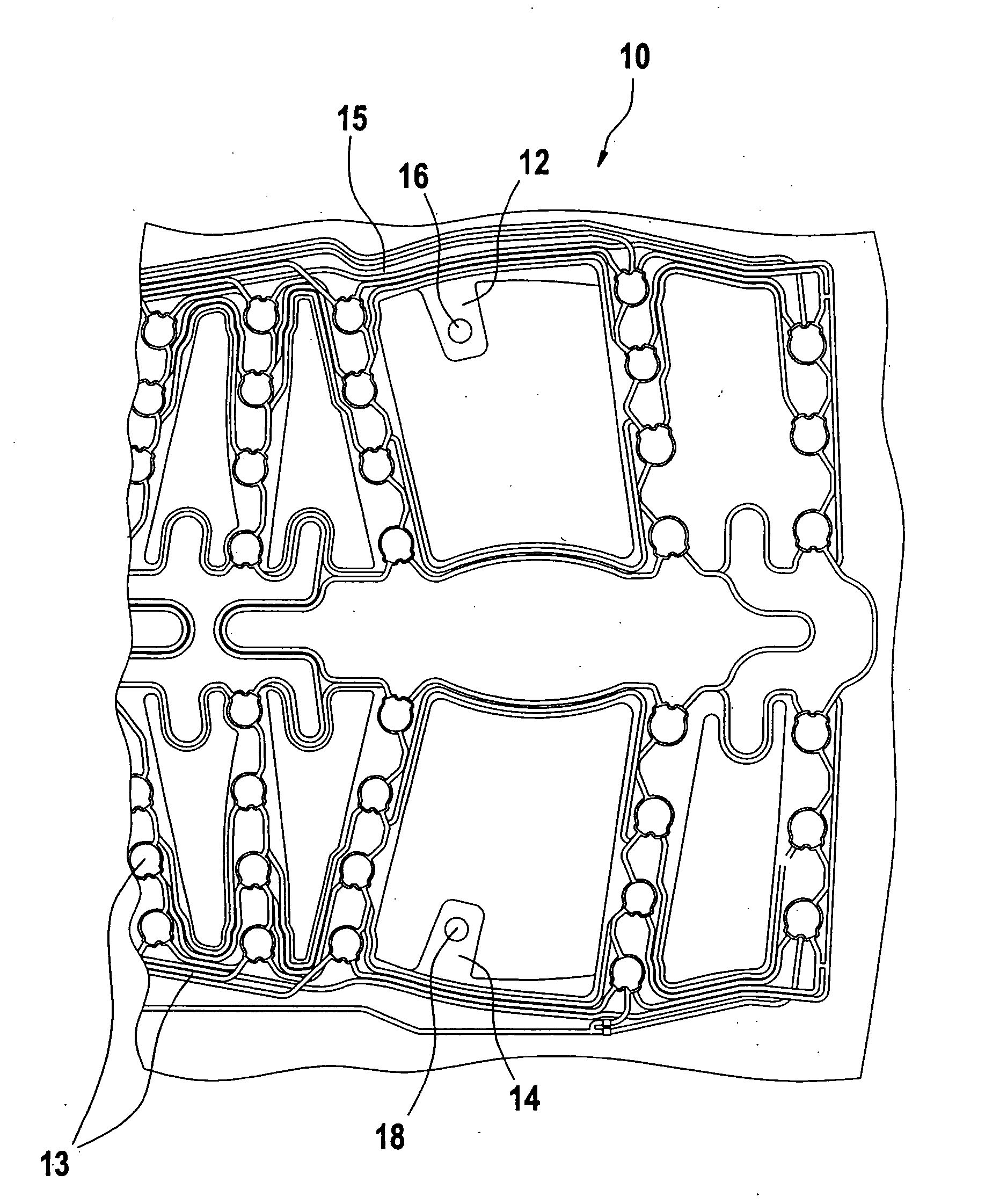
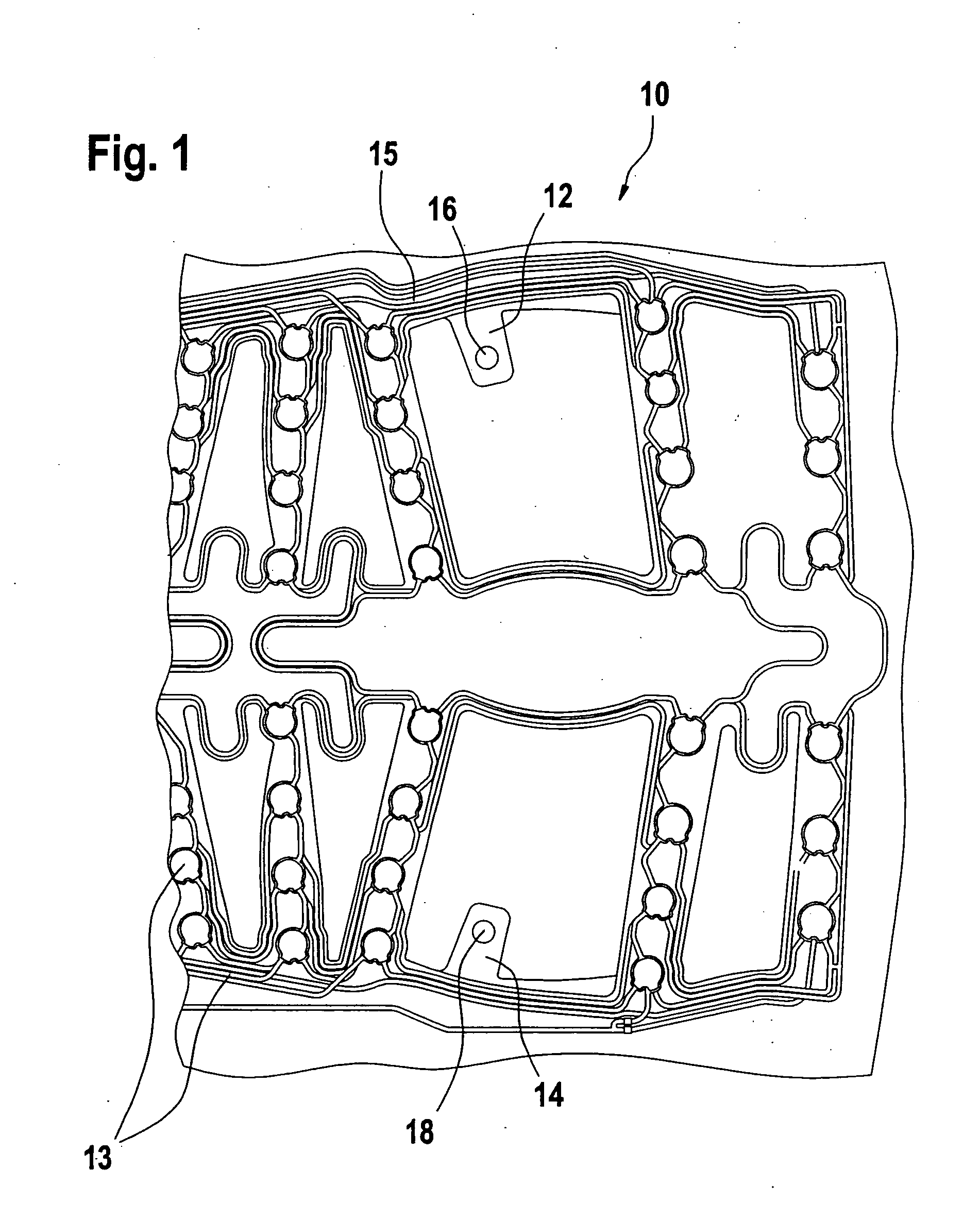
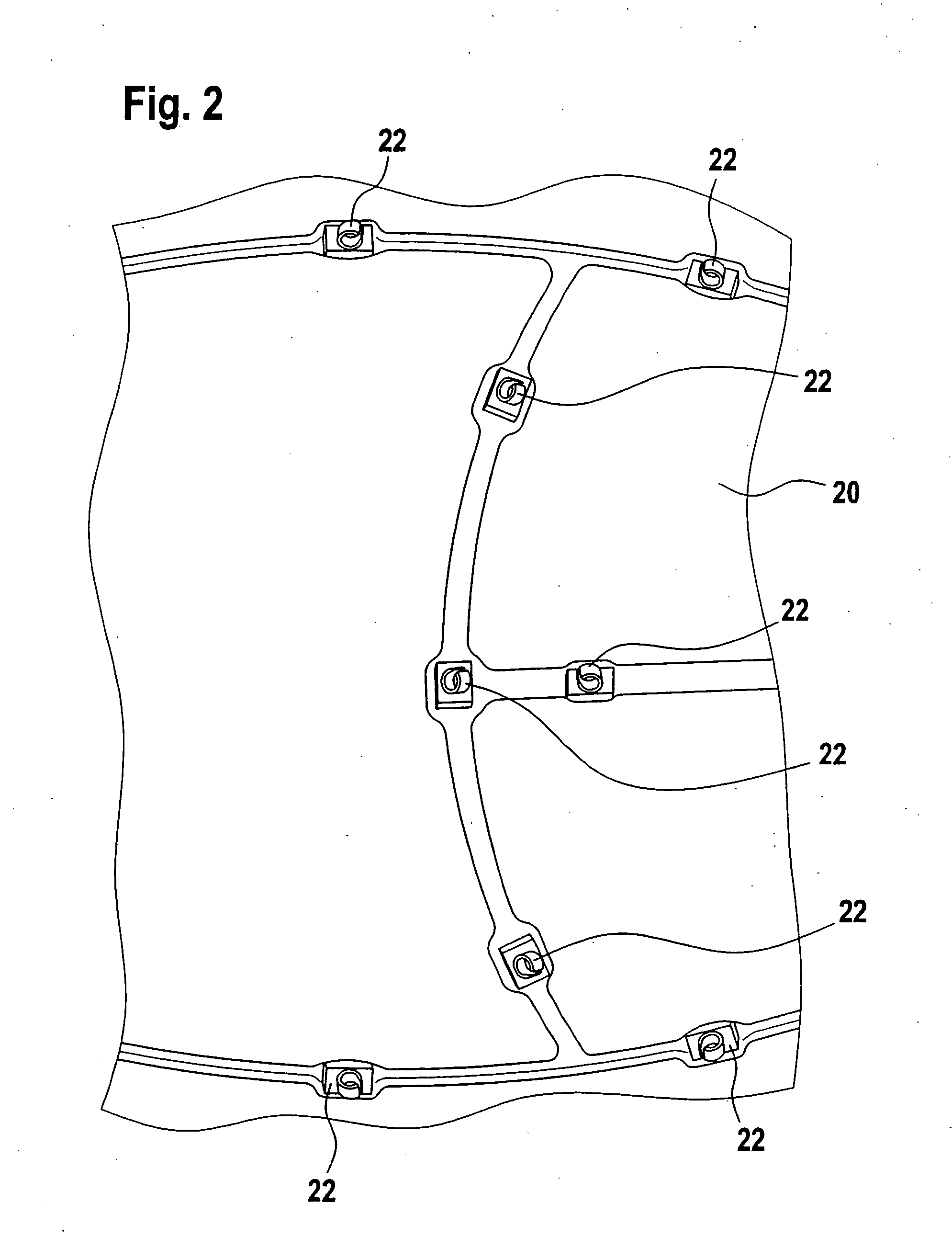
[0014] On the sensor mat there are provided positioning strips having suitable openings for snapping into place into the devices for fixing on the cover (e.g. wing clips). The openings in the positioning strips are formed in such a way that a secure snapping in is ensured, e.g. using the wing clips. The positioning strips are connected to the mat in such a way that the sensor mat is positioned in the setpoint position by snapping into, for instance, the wing clips.

[0015]FIG. 1 shows a sensor mat 10 which, in the embodiment shown, has two positioning strips 12 and 14. The positioning strips are a part of sensor map 10, in this instance. The positioning strips are stamped during the manufacturing of the sensor mat, which is also stamped, of the base material for the sensor mat, together with carrier structure 15 for the electrical parts. Electrical structures 13 are then printed onto the carrier structure of the sensor mat. Consequently, fitting measures, such as adhesion, etc., are ...


PUM


Abstract

A sensor mat, particularly for vehicle seats in connection with means of restraint, which includes at least one positioning strip that may be snapped onto a fastening means.

Description

FIELD OF THE INVENTION [0001] The present invention relates to a sensor mat, especially for passenger classification and / or passenger detection in connection with restraint systems. BACKGROUND INFORMATION [0002] Systems for passenger classification are used in the automotive field. These systems are based, among other things, on sensor mats that are connected with an evaluation electronics system, and that are built into the vehicle seat cushion. They supply an output signal that corresponds to the weight of the person on the seat, which is evaluated for the weight-dependent control of the restraint systems by the air bag control unit. When the seat is unoccupied, the triggering of the means of restraint is forestalled. [0003] At this time, there are various methods to fix this sensor mat, when installing it in the seat cushion, in a setpoint position in such a way that it cannot slip out of place during the fixing on of the seat cover. This is important, since a sensor mat that has...

Claims


Application Information

Patent Timeline
Patent Type & Authority Applications(United States)
IPC IPC(8): A47C31/12B60N2/00B60R21/01B60R21/015G01G19/414
CPCB60N2/002B60R21/01516G01G19/4142
Inventor SCHMIED, MARTINHENNE, RALFJUNGEN, DIETMARSTEIER, ANDREASWITTMANN, BJORN
Owner ROBERT BOSCH GMBH
Why Eureka
Try Eureka