Eureka AIR delivers breakthrough ideas for toughest innovation challenges, trusted by R&D personnel around the world.

Multiprocessing apparatus

a multi-processing and apparatus technology, applied in the field of multi-processing apparatuses, can solve the problems of unnecessary data storage into the cache, unfavorable local characteristics of the typical multi-processor snoopy cache system, and the inability to meet the requirements of the local cache, so as to reduce the cache miss occurrence ratio of the respective local cache and reduce the contention of shared bus

Inactive Publication Date: 2006-03-16
PANASONIC CORP
View PDF3 Cites 31 Cited by
  • Summary
  • Abstract
  • Description
  • Claims
  • Application Information

AI Technical Summary

Benefits of technology

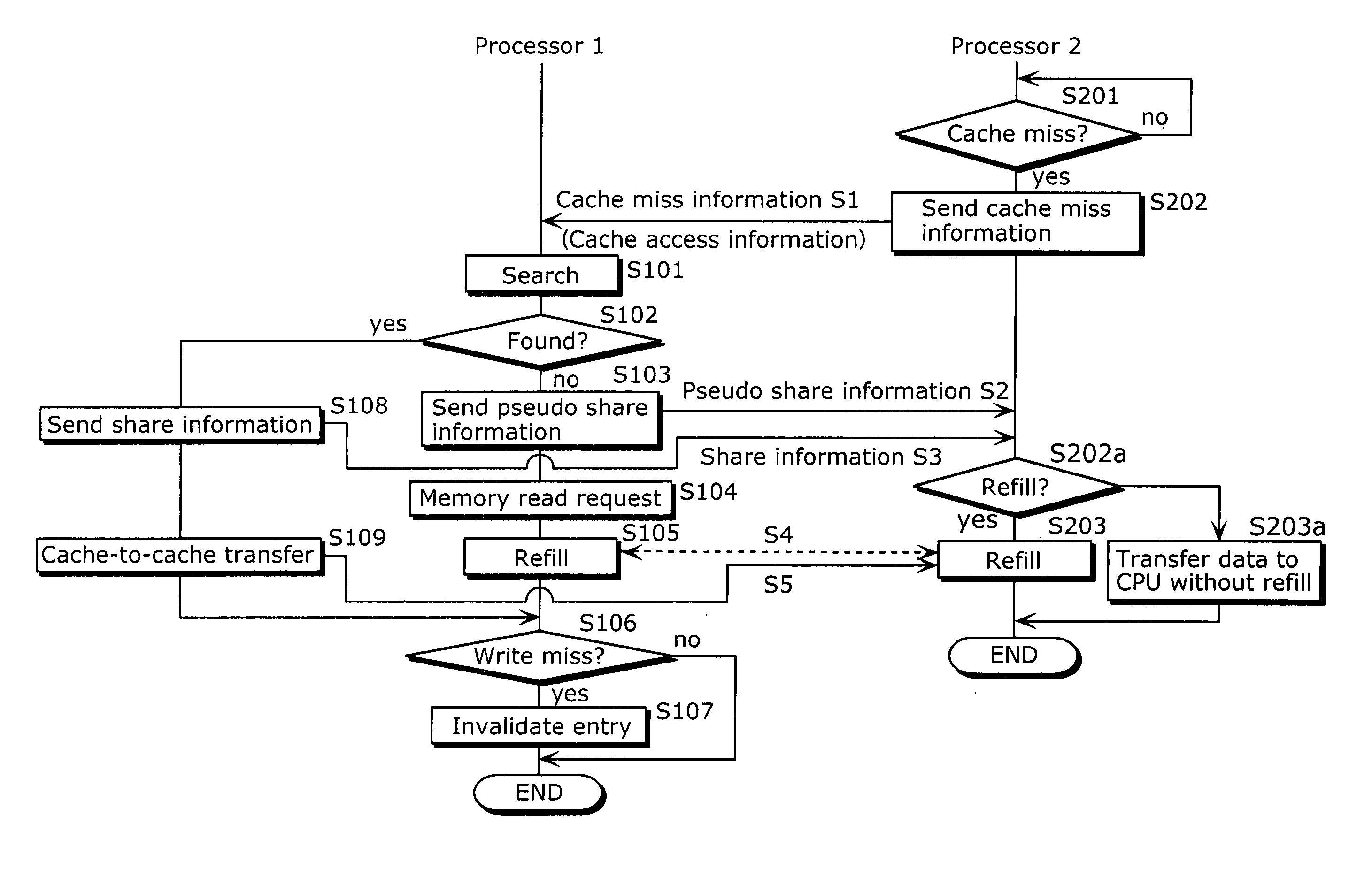
[0012] An object of the present invention is to provide a multiprocessing apparatus that is capable of reducing the cache miss occurrence ratio of the respective local caches, even in the case where there are plural CPUs referring to the same data, and reducing shared bus contentions attributable to cache-to-cache data transfer. This object is achieved by causing a second local cache monitoring the shared bus to perform, in parallel, (i) a notification of pseudo share (pseudo cache hit) information to a first local cache that has issued a cache refill request and (ii) reading of target data from the external memory to refill the cache memory of the second local cache, so that cache refill operations are performed simultaneously to two or more local caches.
[0013] Another object of the present invention is to provide a multiprocessing apparatus that is capable of reducing the cache miss occurrence ratio of the respective local caches, even in the case where there are plural CPUs referring to the same data, and preventing unnecessary cache-to-cache copy of data by determining whether to use pseudo share (pseudo cache hit) information depending on instruction. This object is achieved by causing a second local cache monitoring the shared bus to perform, in parallel, (i) a notification of pseudo share information to a first local cache that has issued a cache refill request and (ii) reading of target data from the external memory to refill the cache memory of the second local cache, and by determining whether to perform cache refill operations simultaneously to two or more local caches by use of the pseudo share information depending on the type of an instruction for performing an access to such first local cache.
[0014] Another object of the present invention is to provide a multiprocessing apparatus that is capable of reducing the cache miss occurrence ratio of the respective local caches, even in the case where there are plural CPUs referring to the same data, and preventing unnecessary cache-to-cache copy of data without having to add any instruction sets. This object is achieved by causing a second local cache monitoring the shared bus to perform, in parallel, (i) a notification of pseudo share (pseudo cache hit) information to a first local cache that has issued a cache refill request and (ii) reading of target data from the external memory to refill the cache memory of the second local cache, and by determining whether to perform cache refill operations simultaneously to two or more local caches by use of the pseudo share information depending on a mode signal from a register storing a processor status of the CPU that has accessed such first local cache.

Problems solved by technology

This is because each local cache performs a cache-to-cache data transfer only for the purpose of maintaining data coherence among the caches, and there is therefore a possibility that unnecessary data is stored into the cache in the case where a cache refill is performed by such another CPU.
In other words, since even when one CPU performs a cache refill, another CPU performs no cache refill, and thus a cache miss occurs at a point on time when a task is assigned to such another CPU in task scheduling, although the same cache access would result in a cache hit in the case of the uniprocessor architecture.
However, a typical multiprocessor snoopy cache system is considered to be inferior to the uniprocessor cache system in terms of local characteristics.

Method used


Image

  • Multiprocessing apparatus
  • Multiprocessing apparatus
  • Multiprocessing apparatus

Examples


first embodiment

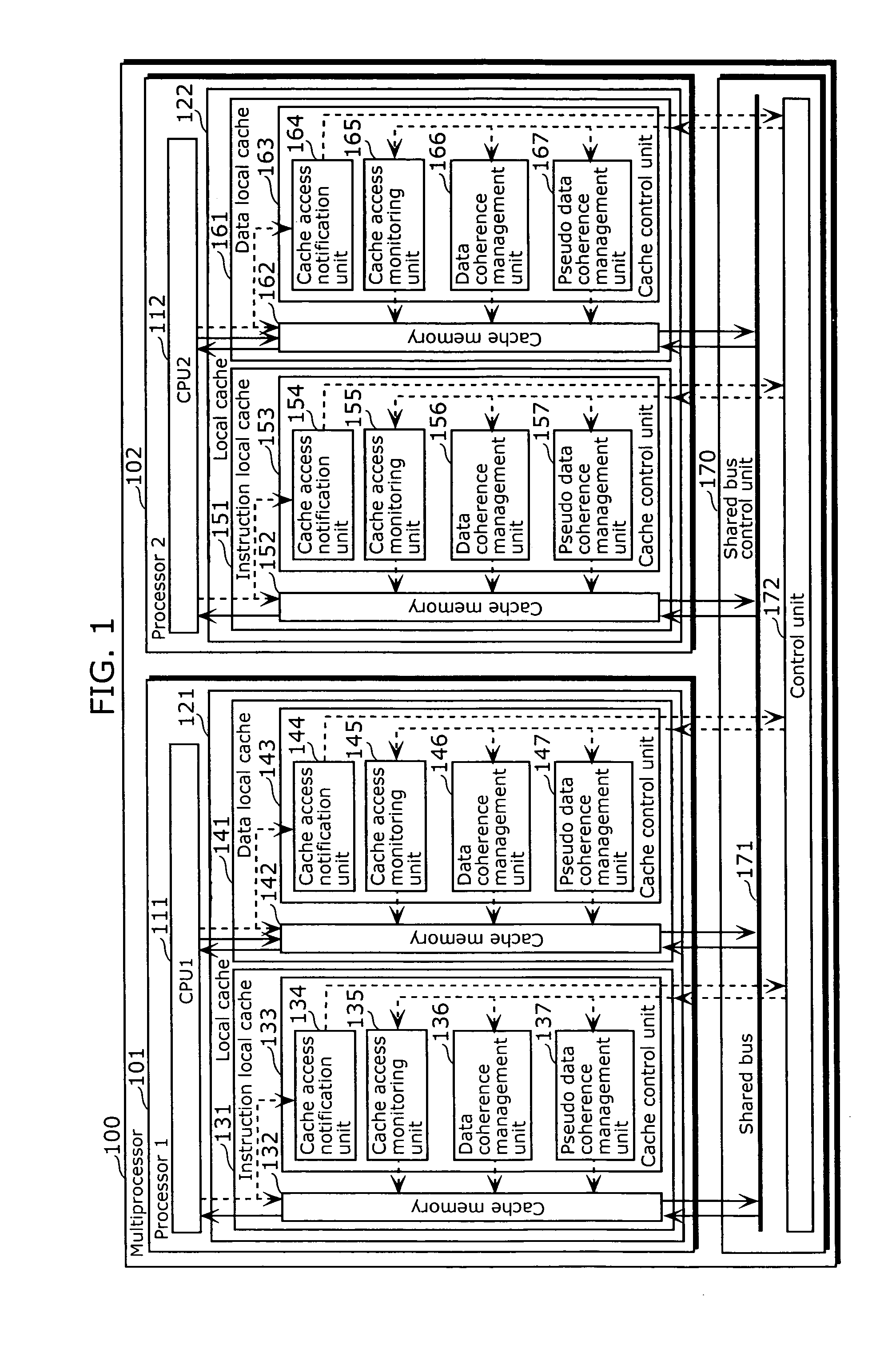
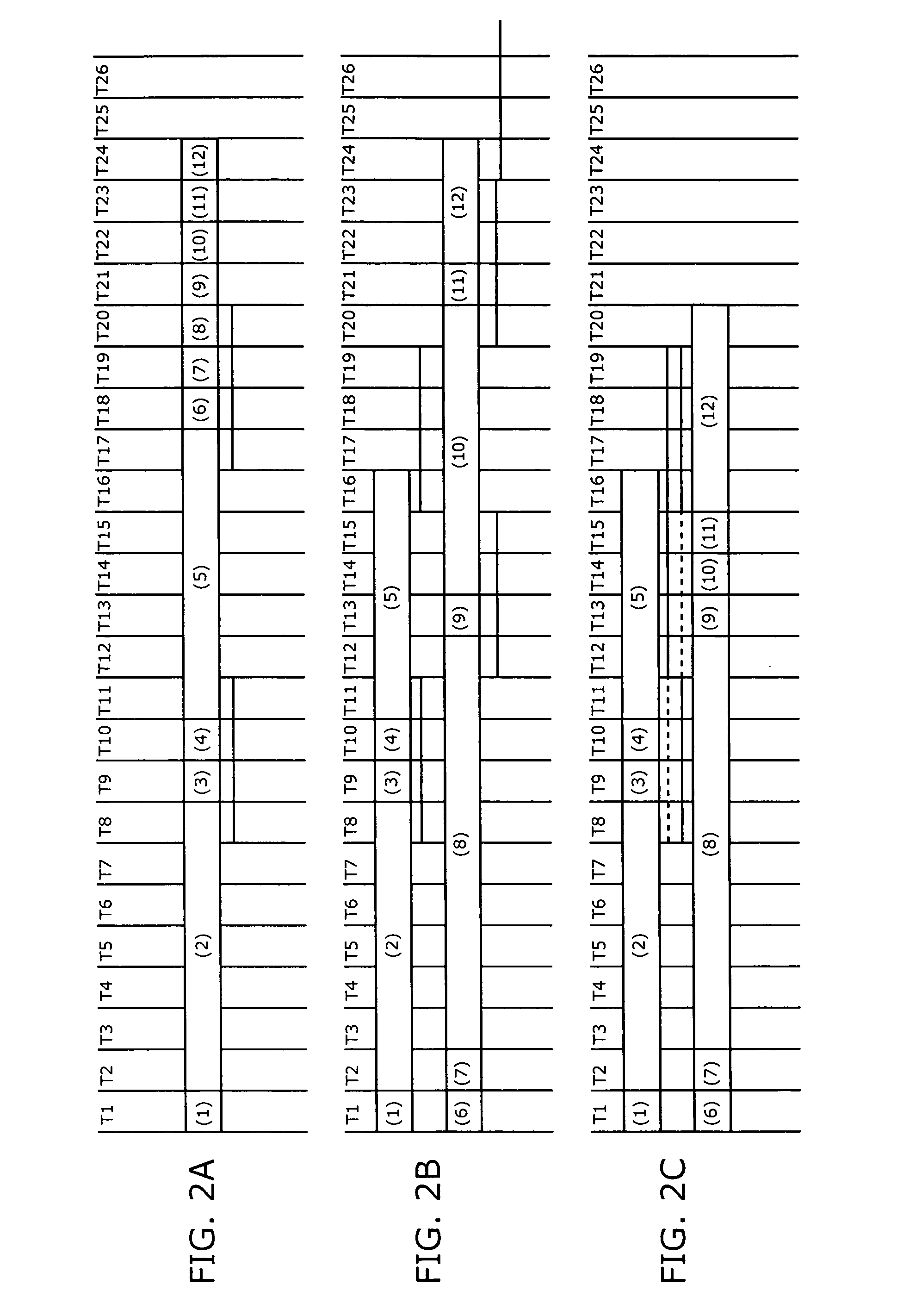
[0077] Referring to FIG. 1, FIGS. 2A to 2C, FIG. 13, and FIG. 15A, a preferred embodiment of the multiprocessor is described.

[0078]FIG. 1 is a functional block diagram showing the multiprocessor according to the present embodiment. FIG. 1 depicts a multiprocessor 100 in which two processors are connected to a shared bus control unit that is made up of a shared bus and a control unit thereof. Processors 101 and 102 include CPUs 111 and 112 as well as local caches 121 and 122, respectively. The local caches 121 and 122 include instruction local caches 131 and 151 as well as data local caches 141 and 161, respectively. The instruction local caches 131 and 151 as well as the data local caches 141 and 161 include cache memories 132, 142, 152, and 162 as well as cache control units 133, 143, 153, and 163 thereof, respectively. The cache control units 133, 143, 153, and 163 include the following units, respectively: data coherence management units 136, 146, 156, and 166 that (i) manage tr...

second embodiment

[0141] However, in the case where the operations of the above-described pseudo data coherence management units are kept enabled at all times, while it is possible to prevent the decrease in cache locality, it is considered that there occurs a problem related to the reduction in cache capacity since the rate of data sharing increases. In view of this, referring to FIG. 3, FIG. 4, and FIG. 15B showing a program 2, a description is given of a multiprocessor that does not make an unnecessary shared use of cache capacity as compared with the first embodiment.

[0142]FIG. 3 is a functional block diagram showing the multiprocessor according to the present embodiment. In the multiprocessor of the present embodiment, CPUs 311 and 312 further include first pseudo data coherence management request units 381 and 382, respectively, in addition to the constituent elements of the multiprocessor shown in FIG. 1. The first pseudo data coherence management request units 381 and 382 are connected to th...

third embodiment

[0161] However, the addition of instruction codes results in a problem of compatibility and the like since such addition is equivalent to changing of the architecture. In view of this, referring to FIG. 3, FIG. 5, and FIG. 15A showing the program 1, a description is given of a multiprocessor that reduces a wasteful use of cache capacity (shared use of unnecessary data) without adding any special set of instructions, as compared with the second embodiment.

[0162]FIG. 5 is a diagram showing the structure of each of the first pseudo data coherence management request units 381 and 382 shown in FIG. 3. FIG. 5 depicts functional blocks related to each of the first pseudo data coherence management request units 381 and 382 in the respective CPUs 311 and 312 shown in FIG. 3. Each CPU 500 includes: a load / store access address generation unit 501 that generates a load / store access address 502 when a load / store access is performed; a processor status storage unit 510 that indicates a status of...


PUM


Abstract

The multiprocessing apparatus of the present invention is a multiprocessing apparatus including a plurality of processors, a shared bus, and a shared bus controller, wherein each of the processors includes a central processing unit (CPU) and a local cache, each of the local caches includes a cache memory, and a cache control unit that controls the cache memory, each of the cache control units includes a data coherence management unit that manages data coherence between the local caches by controlling data transfer carried out, via the shared bus, between the local caches, wherein at least one of the cache control units (a) monitors a local cache access signal, outputted from another one of the processors, for notifying an occurrence of a cache miss, and (b) notifies pseudo information to the another one of the processors via the shared bus controller, the pseudo information indicating that data corresponding to the local cache access signal is stored in the cache memory of the local cache that includes the at least one of the cache control units, even in the case where the data corresponding to the local cache access signal is not actually stored.

Description

BACKGROUND OF THE INVENTION [0001] (1) Field of the Invention [0002] The present invention relates to a multiprocessing apparatus, and particularly to a technology that is effective when applied to the case where an arbitrary local cache is used out of those of plural processors in a semiconductor chip. [0003] (2) Description of the Related Art [0004] In a conventional symmetric multiprocessor, the respective local caches of processors are connected via a shared bus that is connected to a shared memory. According to a typical cache control method for such conventional symmetric multiprocessor, even when one CPU performs a cache refill to its local cache, another CPU performs no cache refill to its local cache. This is because each local cache performs a cache-to-cache data transfer only for the purpose of maintaining data coherence among the caches, and there is therefore a possibility that unnecessary data is stored into the cache in the case where a cache refill is performed by su...

Claims


Application Information

Patent Timeline
Patent Type & Authority Applications(United States)
IPC IPC(8): G06F12/00
CPCG06F12/0833
Inventor KAKEDA, MASAHIDE
Owner PANASONIC CORP
Why Eureka
Eureka Blog
Learn More