

Laser line projector with spherically rotatable support and level/plumb indicators for the support
a projector and spherical rotation technology, applied in the field of laser line projectors, can solve the problems of limiting the useful length of a projected line, difficulty in forming a projected line of uniform beam intensity along a long wall, and persisting use of manual aimed, small and portable projectors
- Summary
- Abstract
- Description
- Claims
- Application Information
AI Technical Summary
Benefits of technology
Problems solved by technology
Method used
Image

Examples
embodiment 100
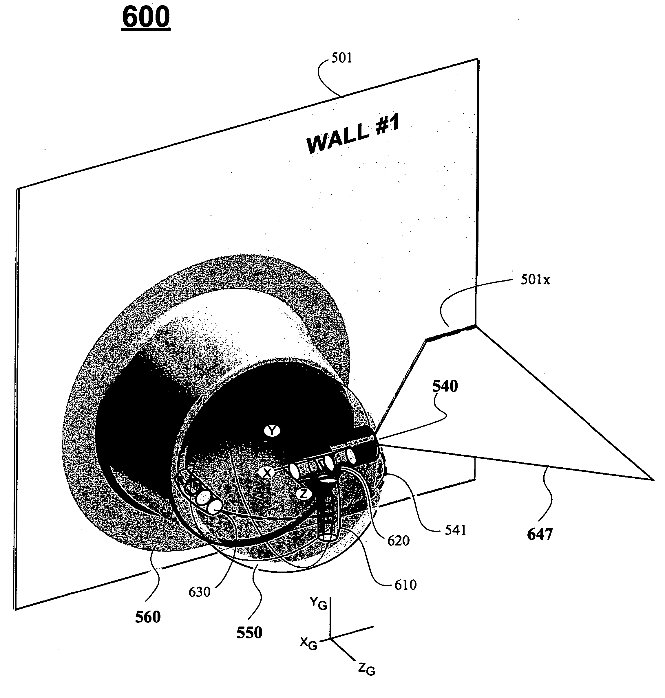
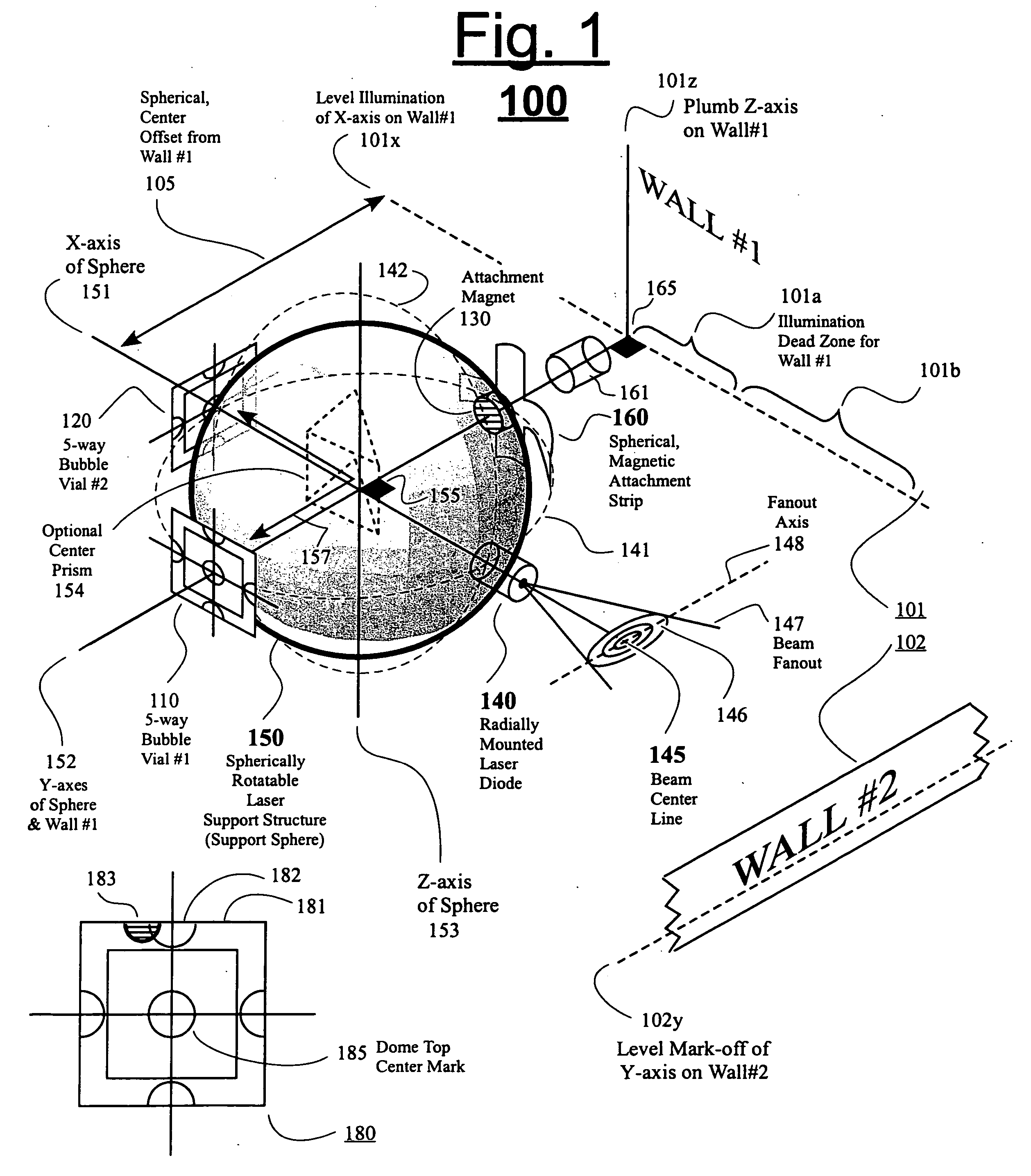
[0027] The cylindrical structure 161 shown extending off wall 101 represents part of a base or pedestal which removably mounts the guiding surface 160 to the adjacent wall 101. The entirety of the pedestal is not shown so that various guidelines can be better seen. Movement guide 160 is similarly shown as a cross-haired structure rather than in its entirety so that various guidelines can be better seen and appreciated. See also FIG. 2 and FIG. 5 for a clearer understanding of how the base and its moving guide portion may be structured in some embodiments. In the embodiment 100 of FIG. 1, the movement guide 160 is mounted to the pedestal stem 161 and the movement guide 160 is made of a ferromagnetic material so as to attract an attachment magnet 130 provided inside the spherical support structure 150. The internal attachment magnet 130 urges the support 150 towards engagement with the movement guide 160 (so that support 150 does not fall out of guide 160 when not pressed into place b...
embodiment 200
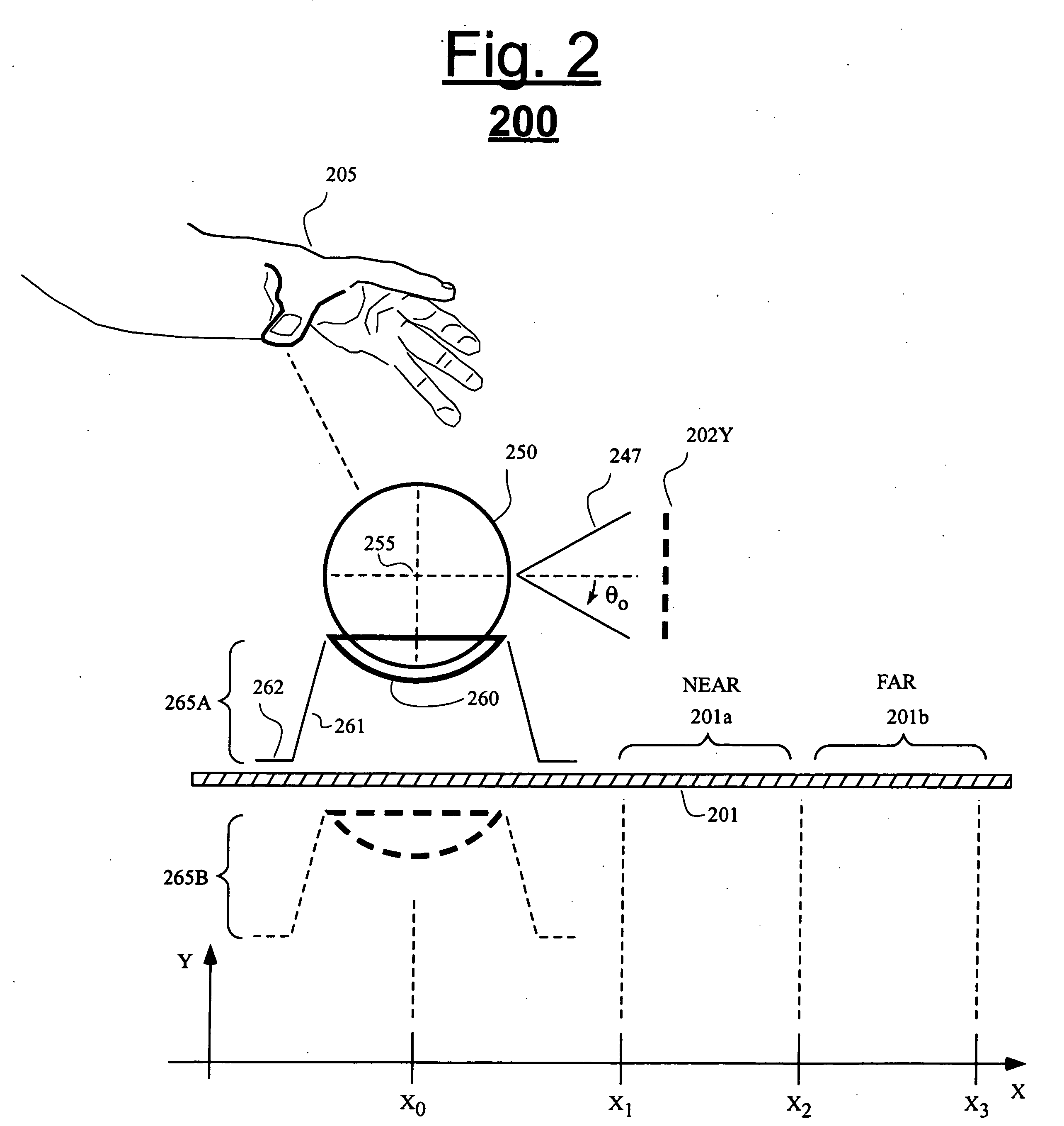
[0033]FIG. 2 shows a schematic top cross sectional view of an embodiment 200 in accordance with the invention. Wall section 201 extends both laterally in the X direction and vertically in the Z direction (not shown). A base unit 265A is removably mounted to the wall 201 to extend outwardly in the Y direction. As seen, the base unit 265A includes a cup-shaped guide 260 that is dimensioned to receive spherical support unit 250 and guide the rotation of support unit 250 spherically about center point 255. Magnets may hold the support unit 250 in cup-shaped guide 260 and / or the workman's hand may urge it that way and / or the cup may extend beneath the support so that gravity keeps the support urged into the receiving cup 260.
[0034] The pedestal or base 265A that mounts to the wall (or other surface, i.e. ceiling, floor) may be structured symmetrically so that it is easily stacked with other alike units such as 265B (shown in phantom behind wall 201). Therefore a plurality of such bases 2...
embodiment 400
[0039] Only one, five-way bubble vial 410 is provided in the illustrated embodiment 400 of FIG. 4. Two projections 458 and 459 extend along the Z-axis of the spherical housing 450 to control the degrees of rotational freedom provided to this sphere 450 in different orientations. For example, when the sphere 450 is oriented as shown so that projection 458 is adjacent to guide extension 468, the sphere 450 is prevented from rotating in the C direction about X-axis 451 by more than a negligible amount. Projections 458 and 459 may have chamfered (keyed) surfaces that determine the amount of movement that will be allowed when the support 450 is in certain angled orientations. The keyed surfaces of projections 458 and / or 459 can be used to prevent a workman from accidentally rotating a projected beam 447 out of a leveled orientation without realizing it. Since the single 5-way level indictor 410 is not sufficient to guarantee that major plane 441 is in a level condition, plumb indicators ...
PUM
 Abstract
Description
Claims
Application Information