LED sign with continuous illumination effect

a technology of led signs and illumination effects, applied in the field of led signs with continuous illumination effects, can solve the problems of generating a large amount of heat while operating, unnecessary yet inevitable rise of user's operating costs, and a loss-lose situation

Inactive Publication Date: 2006-03-23
PAN FR
View PDF12 Cites 18 Cited by
  • Summary
  • Abstract
  • Description
  • Claims
  • Application Information

AI Technical Summary

Benefits of technology

[0010] A main object of the present invention is to provide a LED sign which is capable of forming a uniform line of light source from a plurality of LED illuminators for highlighting a particular character, such as an advertisement sign.

Problems solved by technology

However, these cannot be taken to mean that they are free from disadvantages.
In fact, some people are actually forced to tolerate those disadvantages and continue using them simply because they cannot find suitable alternatives.
A major disadvantage of conventional light boxes and neon lights is that they generate a large amount of heat while operating.
Not to mention safety problem resulting from such heat, this large amount of heat itself represents a serious waste of large amount of energy which in turns reflects in unnecessary yet inevitable rise of the user's operating cost.
Thus it comes to a lose-lose situation that the user pays higher for more serious loss of natural resources (electricity) without gaining any extra economic profit.
Another disadvantage is that conventional neon light or fluorescent light box is extremely fragile to physical impact.
This not only increases the cost of handling such products, but also presents a potential risk to those handling or purchasing the products.
However, there exist some inherent disadvantages for using LEDs.
For example, despite the fact that LED is more long-lasting and economically more efficient, light from each particular LED is not generally strong enough for highlighting an advertisement or business signs.
However, as each LED represents a single point source of light, each light box eventually comes up with a plurality of discrete light sources and the overall illumination effect is far from satisfactory.
Thus, the problem of how to convert what is originally discrete single points of light source to a continuous line of light source is a pressing problem for engineers.

Method used


Image

  • LED sign with continuous illumination effect
  • LED sign with continuous illumination effect
  • LED sign with continuous illumination effect

Examples


Embodiment Construction

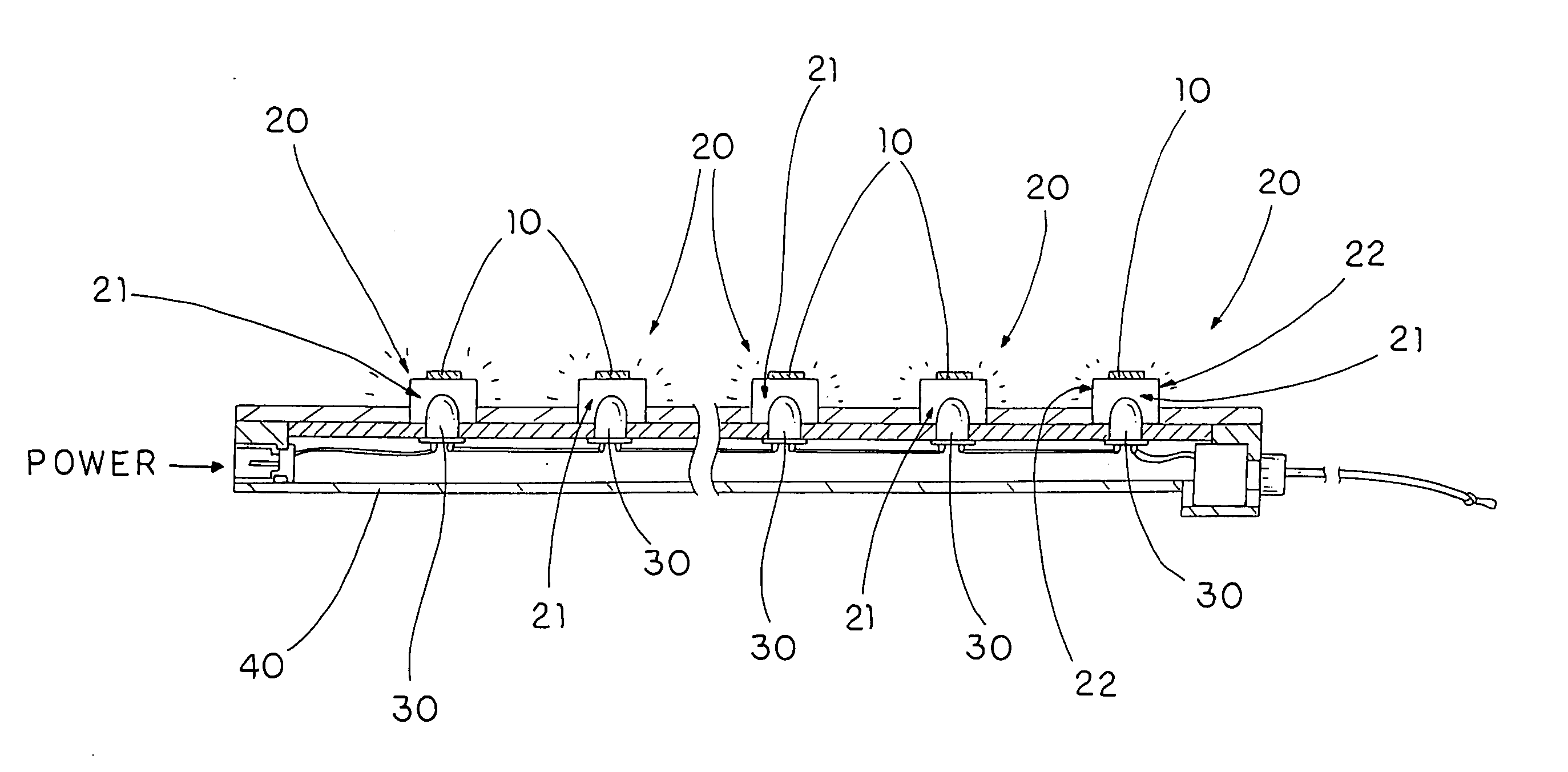
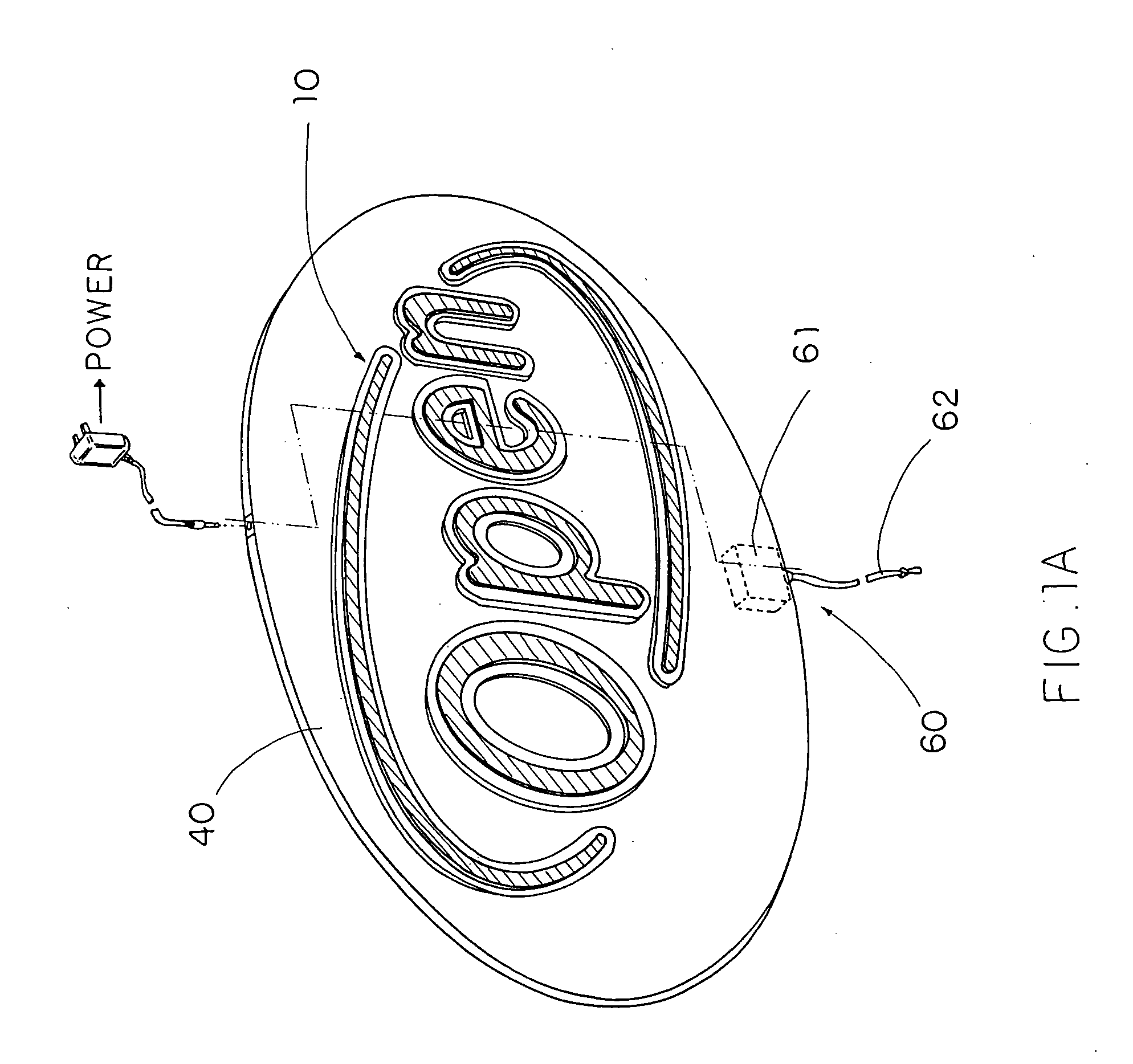
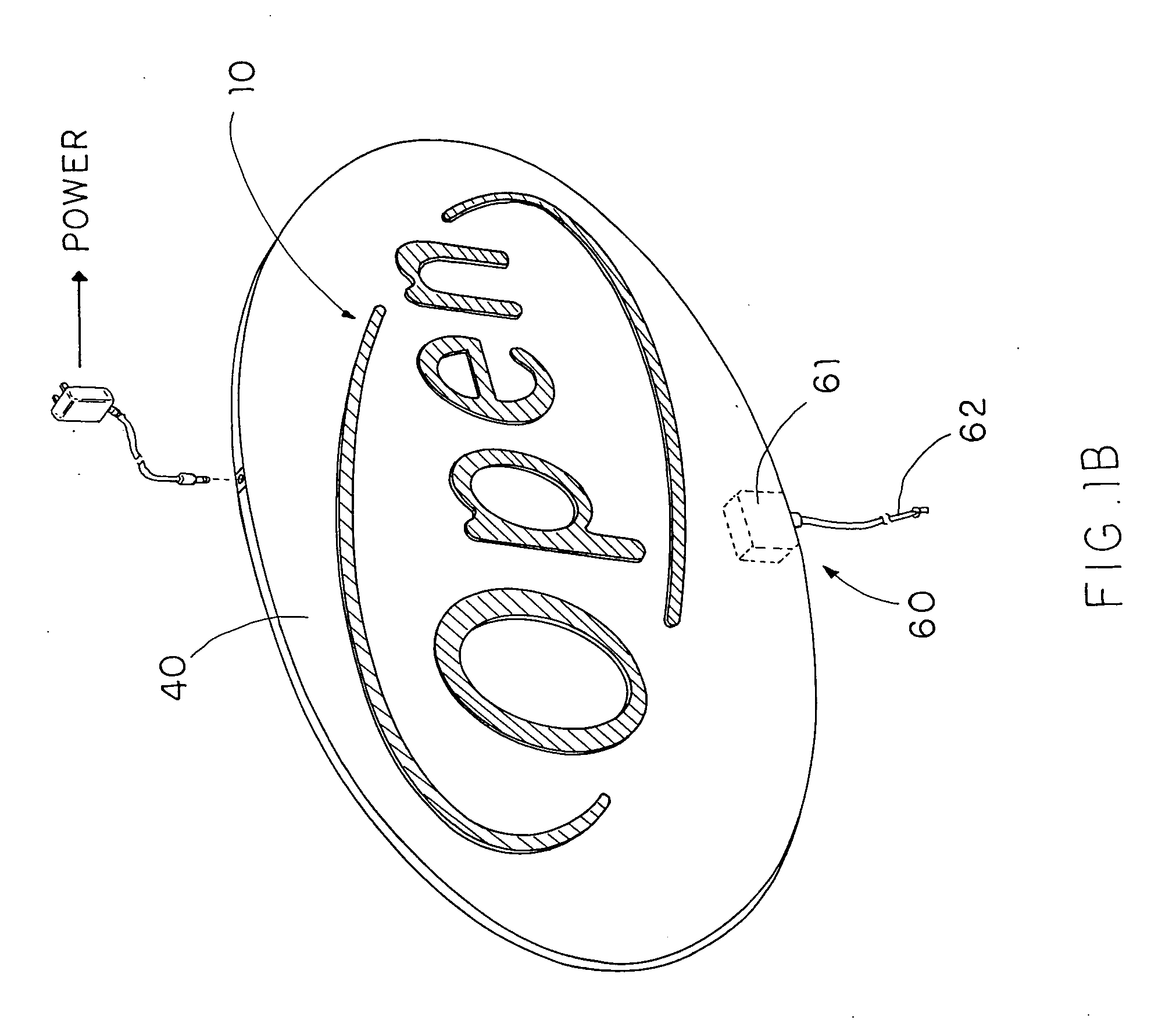
[0032] Referring to FIG. 1A of the drawings, a LED sign according to a preferred embodiment of the present invention is illustrated, in which the LED sign comprises a figure sign 10, at least one light guider 20, and a plurality of LED illuminators 30.

[0033] The figure sign 10 is shaped as forming a particular character having a predetermined light transmisivity and color. For example, the figure sign 10 may be embodied as a ‘O’ character in which it may be coated with a particular color for particular purpose, such as for use in a particular advertisement campaign. In addition, the figure sign 10 can be shaped as a line, character, number, or even an aesthetic figure to incorporate with the light guider 20.

[0034] The light guider 20 is shaped corresponding to the figure sign 10, wherein it is overlappedly supported on a central portion of a front side of the light guider 20 and optically communicated with the illumination channel 21. Moreover, the light guider 20 further has a pl...


PUM


Abstract

A LED sign includes at least a light guider, which is shaped as a sign word, defining an illumination channel therealong and a plurality of LED illuminators spacedly disposed underneath the light guider at a light diffusion distance for generating lights towards the illumination channel in such a manner that the lights are accumulated within the illumination channel to highlight the light guider so as to form a continuous illumination effect as a neon light effect.

Description

CROSS REFERENCE OF RELATED APPLICATION [0001] This is a Continuation-In-Part application of a non-provisional application having an application Ser. No. 10 / 884,583 and filing date of Feb. 19, 2004.BACKGROUND OF THE PRESENT INVENTION [0002] 1. Field of Invention [0003] The present invention relates to a LED (Light Emitting Diode) sign, and more particularly to a LED sign with continuous illumination effect which is capable of forming a line of light source from a plurality of LED illuminators for highlighting particular characters, such as an advertisement sign. [0004] 2. Description of Related Arts [0005] Illuminating devices are widely utilized to perform differing commercial or business tasks. For example, advertisements are highlighted by light boxes so that during night time people can be notified and attracted by sharp and colorful advertisements. Besides, neon signs are usually set up in front of shops showing the opening status of them. [0006] There exist a handful of illumin...

Claims


Application Information

Patent Timeline
Patent Type & Authority Applications(United States)
IPC IPC(8): G09F13/22
CPCG09F13/22
Inventor PAN, FRANK
Owner PAN FR
Why Eureka
Try Eureka