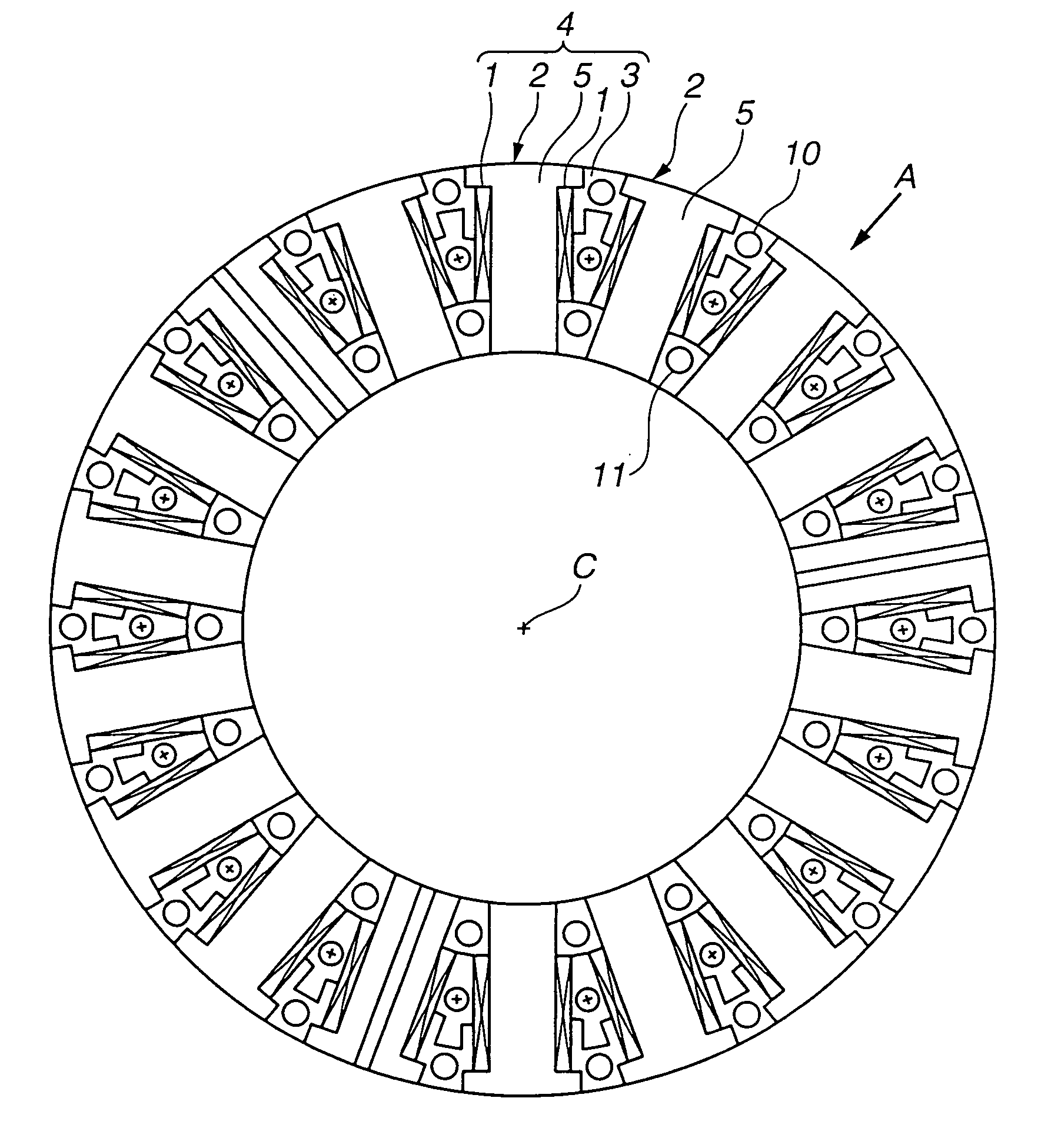
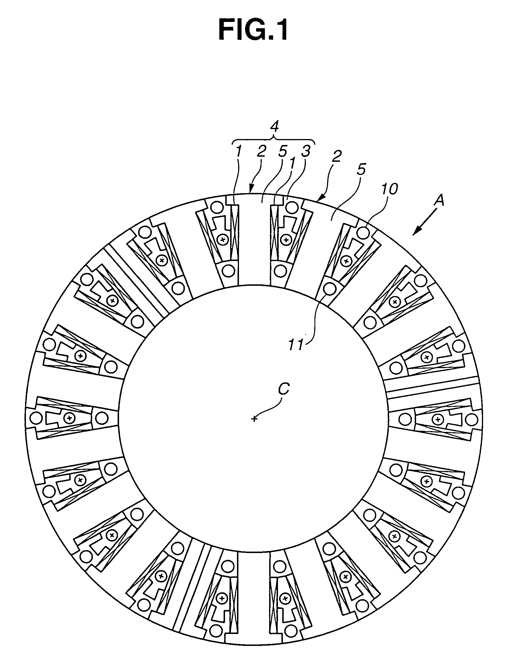
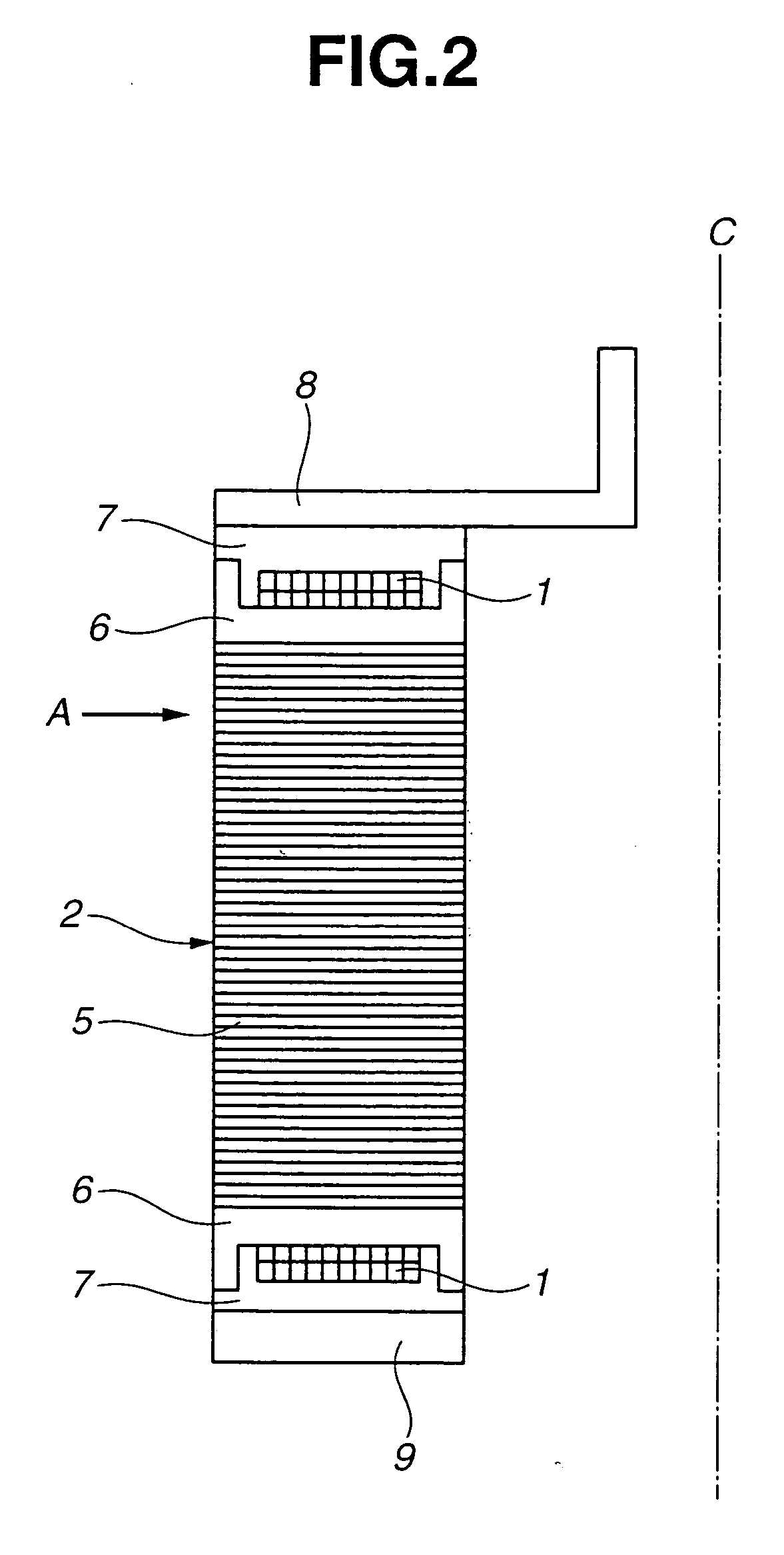
Stator for rotary electric machine
a rotary electric machine and multi-layer technology, applied in the direction of dynamo-electric machines, dynamo-electric components, magnetic circuit shapes/forms/construction, etc., can solve the problem that the stator core cannot be rigidly fixed by the molded resin in neither the radial direction nor the axial direction of the stator core, and the restraining force of the molded resin is deteriorated
- Summary
- Abstract
- Description
- Claims
- Application Information
AI Technical Summary
Benefits of technology
Problems solved by technology
Method used
Image
Examples
third embodiment
[0034]FIG. 6B illustrates a modification of the third embodiment in which projection 302B is provided on a radially inner side of opposed side surfaces of the shank portion of stator core 302 and forms the meshing portion on the side surfaces of stator core 302. Projection 302B continuously extends in the direction of central axis C of the stator between opposite axial end surfaces of stator core 302. Specifically, projections 302B are formed on a radially inner side of circumferentially opposed side surfaces of the shank portion of respective stator segments 305 laminated in the direction of central axis C. Projections 302B are in alignment with one another in the direction of central axis C. Molded resin 303 is filled between adjacent stator cores 302 and formed with a recess meshed with projection 302B of stator core 302. Owing to the meshing between projection 302B of stator core 302 and the recess of molded resin 303, stator core 302 can be radially fixed and prevented from bei...
fourth embodiment
[0036]FIG. 7B illustrates a modification of the fourth embodiment in which projection 502D is provided on opposed side surfaces of the head portion of stator core 502. Projection 502D continuously extends in the direction of central axis C of the stator between opposite axial end surfaces of stator core 502. Projection 502D forms the meshing portion on the circumferentially opposed side surfaces of stator core 502 which is meshed with molded resin 503 filled between adjacent stator cores 502. Specifically, projections 502D are formed on circumferentially opposed side surfaces of the head portion of respective stator segments 505 laminated in the direction of central axis C. Projections 502D are in alignment with one another in the direction of central axis C. Molded resin 503 filled between adjacent stator cores 502 are formed with a recess meshed with projection 502D of stator core 502.
[0037] Owing to the meshing between recess 402C of stator core 402 and the projection of molded r...
fifth embodiment
[0039] Owing to the meshing between cutout 602E of stator core 602 and the projection of molded resin 603 in the fifth embodiment, stator core 602 can be radially fixed and prevented from being radially displaced relative to molded resin 603. Further, in the presence of cutout 602E, an air gap between stator core 602 and the outer rotor is stepwise varied in the vicinity of the circumferentially opposed side surfaces of the head portion of stator core 602. As a result, dispersion in magnetic attraction force produced between the stator and the outer rotor which is caused depending on the rotational position of the outer rotor can be considerably reduced, to thereby suppress the cogging torque which will be caused in the rotary electric machine.
[0040] Referring to FIG. 9, a sixth embodiment of the stator of the present invention is explained, which differs in configuration of the cutout from the fifth embodiment. Cutout 702F is formed at corners in which circumferentially opposed sid...
PUM
 Abstract
Description
Claims
Application Information
 - R&D
- Intellectual Property
- Life Sciences
- Materials
- Tech Scout
- Unparalleled Data Quality
- Higher Quality Content
- 60% Fewer Hallucinations
Browse by: Latest US Patents, China's latest patents, Technical Efficacy Thesaurus, Application Domain, Technology Topic, Popular Technical Reports.
© 2025 PatSnap. All rights reserved.Legal|Privacy policy|Modern Slavery Act Transparency Statement|Sitemap|About US| Contact US: help@patsnap.com


