Multiple testing bars for testing liquid crystal display and method thereof
a liquid crystal display and multi-stage technology, applied in the field of liquid crystal displays, can solve the problems of reducing the protection capability against electrostatic charges and hard to detect short-circuited elements, and achieve the effect of increasing the detection ability of visual defects and increasing reliability
- Summary
- Abstract
- Description
- Claims
- Application Information
AI Technical Summary
Benefits of technology
Problems solved by technology
Method used
Image
Examples
first embodiment
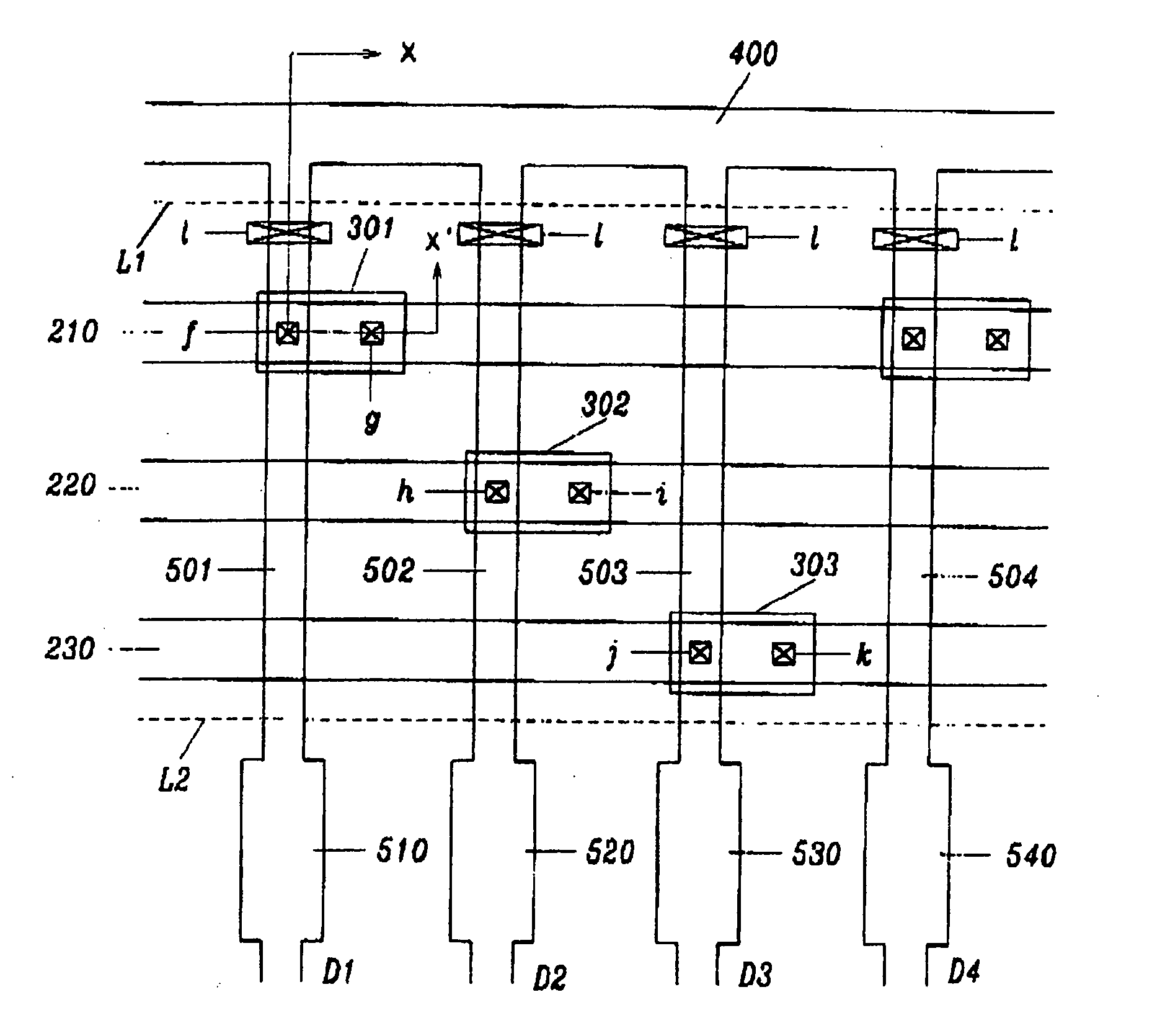
[0080] Then, a visual test method is described with references to FIGS. 13, 14 and 15A to 15C. FIG. 14 illustrates wave forms of array test signals applied to gate and data lines through the respective secondary lines and FIGS. 15A to 15C illustrate polarities of signals applied to R, G, B pixels in modes 1 to 3. As shown in FIGS. 13 and 14, signal voltages Godd and Geven are applied to a plurality of gate lines in odd rows and a plurality of gate lines in even rows. Signal voltages DR, DG and DB are respectively applied to a plurality of (3n-2)th, (3n-1)th and (3n)th data lines through the first to the fifth secondary lines 410, 420, 210, 220 and 230.
[0081] Then, the signal voltages are described more in detail hereinafter. Signal voltages Godd and Geven, which respectively include pulses turning on thin film transistors, are applied to odd gate lines and to even gate lines through the first and the second secondary lines 410 and 420. If the period from the moment one pulse is app...
second embodiment
[0098] In the defect detecting method since polarities of the test signals applied to R, G and B pixel columns invert with the same period as the width of the gate pulse, the signals is not charged into the pixels sufficiently. As a result, flicker effects may occur. In addition, it is not suitable to test for visual uniformity that is usually confirmed by naked eyes, and it is difficult to detect the pixel defects under the high state or off state.
[0099]FIG. 18 shows testing wave forms according to the third embodiment to improve this problem. In FIG. 18, signals DR, DG and DB applied to R, G and B pixel columns and signals Godd and Geven applied to odd and even gate lines are mostly similar to the signals in the second embodiment. Instead, the signals applied to the R, G and B pixel columns invert with a period of two times the width of the gate pulse. Therefore, there is no difficulty in charging the R, G and B signals into the pixels, it is easy to synchronize the gate pulse an...
fourth embodiment
[0100]FIG. 19 illustrates wave forms of array test signals in which pulses are applied to the odd gate lines and to the even gate lines and the two pulses are synchronized with a half frame difference. Test signals invert with a period of twice the width of the gate pulse.
[0101] In the fourth embodiment, the gate pulse is applied later than the moment (t1, t2) when the signals DR, DG and DB applied to the R, G and B pixel columns invert. Therefore, the signals can be charged with a large initial charging value when TFTs are turned on. As a result, the charging time decreases and the signals can be charged sufficiently while the gate pulse is applied. Therefore, it is easy to test even a high resolution substrate.
[0102] As described above, in the LCD according to the present invention, since gate secondary shorting bars or data secondary shorting bars are respectively formed with more than two divided lines and separated from a gate shorting bar and a data shorting bar, the substra...
PUM
| Property | Measurement | Unit |
|---|---|---|
| polarity | aaaaa | aaaaa |
| time | aaaaa | aaaaa |
| width | aaaaa | aaaaa |
Abstract
Description
Claims
Application Information
 - R&D
- Intellectual Property
- Life Sciences
- Materials
- Tech Scout
- Unparalleled Data Quality
- Higher Quality Content
- 60% Fewer Hallucinations
Browse by: Latest US Patents, China's latest patents, Technical Efficacy Thesaurus, Application Domain, Technology Topic, Popular Technical Reports.
© 2025 PatSnap. All rights reserved.Legal|Privacy policy|Modern Slavery Act Transparency Statement|Sitemap|About US| Contact US: help@patsnap.com


