Stereoscopic image display system

a display system and image technology, applied in the field of stereoscopic image display system, can solve the problems of viewer discomfort, inability to view the and inability to fulfill the need of viewing object from the desired angl

Active Publication Date: 2006-03-23
SEIKO EPSON CORP
View PDF16 Cites 135 Cited by
  • Summary
  • Abstract
  • Description
  • Claims
  • Application Information

AI Technical Summary

Benefits of technology

[0052] Since infrared LEDs are available at a low price, the stereoscopic image display system

Problems solved by technology

However, in a conventional stereoscopic image display system, only the position of the glasses is detected while not considering the inclination of the glasses.
For example, when the viewer tilts his head for viewing an object displayed by a certain stereoscopic image display system from beneath, the inclination component of the glasses is not recognized by the stereoscopic image display system, thereby making the viewer unable to view the object from the desired angle, bringing about viewer discomfort

Method used


Image

  • Stereoscopic image display system
  • Stereoscopic image display system
  • Stereoscopic image display system

Examples


first embodiment

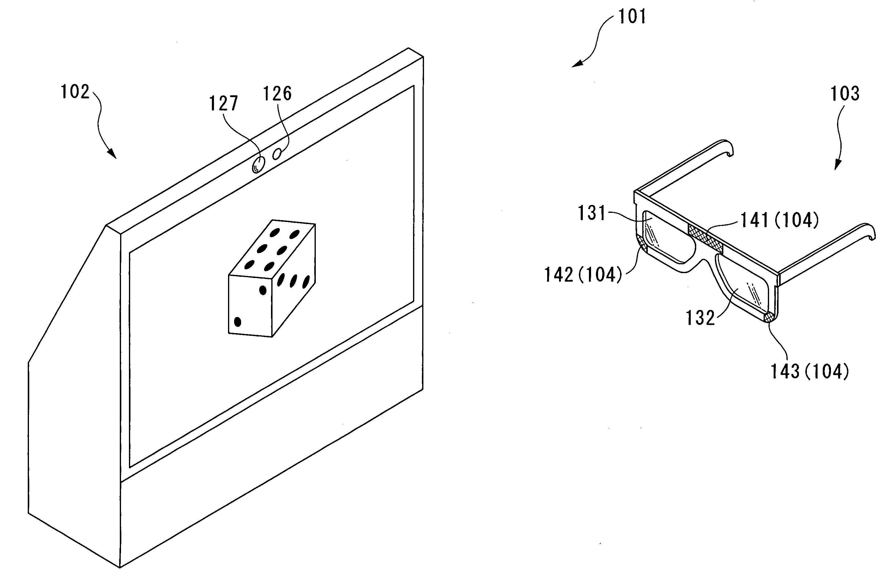
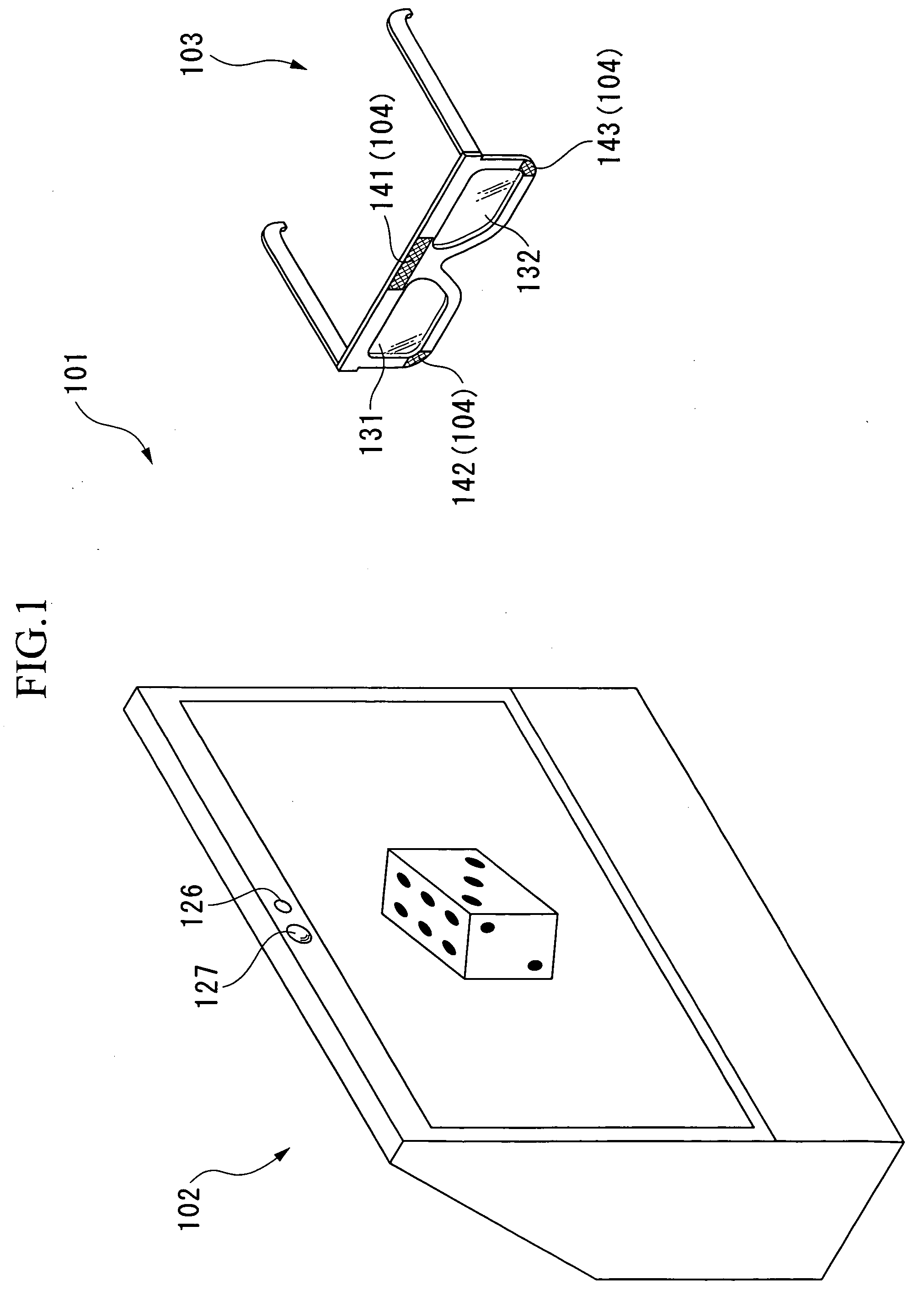
[0131]FIG. 10 is a perspective view illustrating a schematic configuration of the stereoscopic image display system according to the first embodiment of the second aspect of the present invention. As shown in this figure, the stereoscopic image display system 201 of the first embodiment is provided with an image display apparatus 202 and glasses 203.

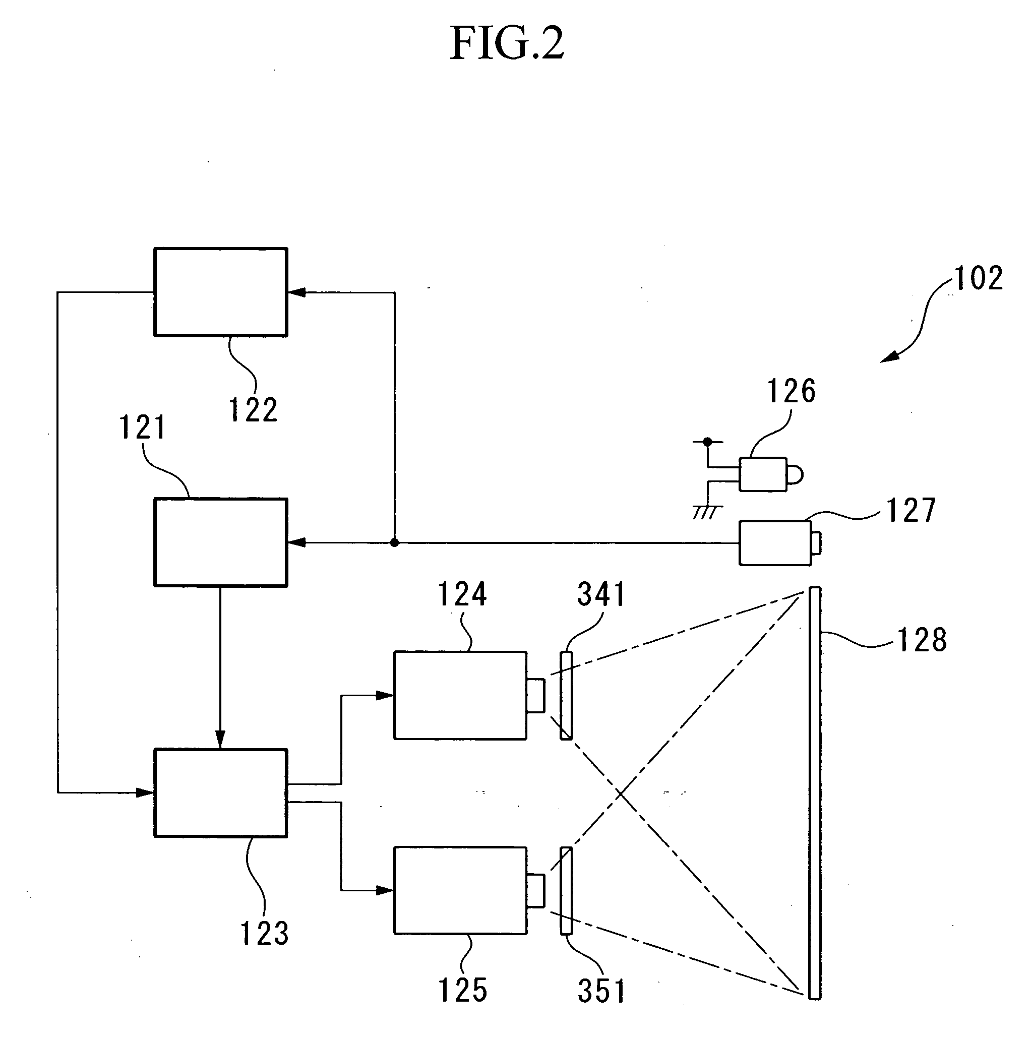
[0132] The image display apparatus 202 displays a parallax image composed of the right eye image and the left eye image, or either of a right eye image and a left eye image of the parallax image. A block diagram illustrating an internal configuration of the image display apparatus 202 is shown in FIG. 11. As shown in FIG. 11, the image display apparatus 202 is configured to be provided with a determination section 221 (determination unit), an image generation section 223 (image generation unit), a parallax image generating section 223 (parallax image generation unit), a projector 224 for the left eye image (display unit), and a projecto...

second embodiment

[0168] Next, the second embodiment of the second aspect of the present invention will be described. The second embodiment differs from the first embodiment only in the method for the put-on / taken-off determination of the glasses 203. Therefore, in the description of the second embodiment, descriptions regarding parts shared with the first embodiment have been omitted or simplified.

[0169] In the stereoscopic image display system of the second embodiment, the operation in Step S12 differs from that in the stereoscopic image display system of the first embodiment.

[0170] Specifically, the determination section 221 of the stereoscopic image display system of the second embodiment, in Step S12, detects the inclination of the glasses 203 from the image obtained in Step S11 and determines whether the glasses 203 are put on or taken off based on the detected inclination of the glasses 203.

[0171] More specifically, the determination section 221 calculates the inclination of the glasses 203...

third embodiment

[0176] Next, the third embodiment of the second aspect of the present invention will be described. The third embodiment also differs from the first embodiment only in the method for the put-on / taken-off determination of the glasses 203. Therefore, in the description of the third embodiment as well, descriptions regarding parts shared with the first embodiment have been omitted or simplified.

[0177] In the stereoscopic image display system of the third embodiment, the operation in Step S12 differs from that in the stereoscopic image display system of the first embodiment.

[0178] Specifically, the determination section 221 of the stereoscopic image display system of the second embodiment, in Step S12, detects the position of the irises of the viewer from the image obtained in Step S11 and determines whether the glasses 203 are put on or taken off based on the detected position of the irises.

[0179] Since the irises of a human reflect light in the direction of its incidence as the retr...


PUM


Abstract

A stereoscopic image display system includes: an image display unit that displays a parallax image composed of a right eye image and a left eye image; glasses having a transmission portion for a right eye transmitting only the right eye image of the parallax image and a transmission portion for a left eye transmitting only the left eye image of the parallax image; an inclination detection unit that detects an inclination of the glasses; a parallax image generation unit that generates the parallax image in accordance with a detection result from the inclination detection unit; and a display unit that displays the parallax image generated by the parallax image generation unit.

Description

BACKGROUND OF THE INVENTION [0001] 1. Field of the Invention [0002] The present invention relates to a stereoscopic image display system. [0003] Priority is claimed on Japanese Patent Applications Nos. 2004-271510 and 2004-271511, filed Sep. 17, 2004, the contents of which is incorporated herein by reference. [0004] 2. Description of the Related Art [0005] A human recognizes a visible object as a stereoscopic image using his / her brain while combining an image viewed by a right eye and an image viewed by a left eye. Since the right and left eyes view the object from different angles, the image viewed by the right eye and the image viewed by the left eye are slightly different from each other, thereby making it possible to achieve this. [0006] Therefore, allowing a viewer to recognize an image displayed two-dimensionally as a stereoscopic image can be achieved by displaying a parallax image composed of the image viewed by the right eye (right eye image) and the image viewed by the lef...

Claims


Application Information

Patent Timeline
IPC IPC(8): H04N13/04H04N13/00H04N15/00H04N9/47H04N13/363
CPCH04N13/0429H04N13/0434H04N13/0438H04N13/0454H04N2213/008H04N13/0475H04N13/0479H04N13/0484H04N13/0459H04N13/337H04N13/341H04N13/378H04N13/332H04N13/363H04N13/373H04N13/359H04N13/383
Inventor SATO, SHIGEMIKUBOTA, AKIRASONEHARA, TOMIO
Owner SEIKO EPSON CORP
Why Eureka
Try Eureka