

Method of drawing image, circuit therefor, and image output control apparatus
a control apparatus and image technology, applied in the direction of digital output to print units, multi-programming arrangements, instruments, etc., can solve the problems of limited processing time and waste of hardware resources, and achieve the effect of reducing the waste of hardware resources
Inactive Publication Date: 2006-03-23
CANON KK
View PDF7 Cites 62 Cited by
- Summary
- Abstract
- Description
- Claims
- Application Information
AI Technical Summary
Benefits of technology
The present invention provides a method of drawing image by a plurality of rasterizing means, each with a dynamic reconfigurable processor capable of executing rasterizing processes in parallel. The method includes generating objects to be drawn with plural kinds of attribute data, generating scheduling data to change the rasterizing processes based on the attribute data, and reconfiguring the processor to change the rasterizing processes based on the scheduling data. The method reduces the waste of hardware resources and performs a high-speed drawing process. The invention also provides a circuit and a print control apparatus for executing the method.
Problems solved by technology
Hence, even when the time of rasterizing process of each attribute changes in drawing each object, or even in an extreme case wherein an attribute without rasterizing process is present, the process time is limited by the rasterizing process of an attribute which always takes time most.
Hence, the hardware resource is wasted.
Method used
View moreImage
Smart ImageViewing Examples

Examples
embodiment
Timing Example of Drawing Process of Embodiment
[0083]FIG. 8 shows an example of reconfiguration of the RM1 to RM4 in FIG. 2 on the basis of the flowchart in FIG. 6.
[0084] Unlike FIG. 4 of the above-described embodiment, reconfiguration starts from “pattern (GD)” and “color (BG)”, i.e., attributes which most take the process time for obj.1. After the reconfiguration is ended, the processing circuits for the attributes “area (AR)” and “outline (MSK)” are reconfigured.
[0085] When reconfiguration scheduling is executed in this way, the rasterizing process can be executed faster.
Login to View More PUM
 Abstract
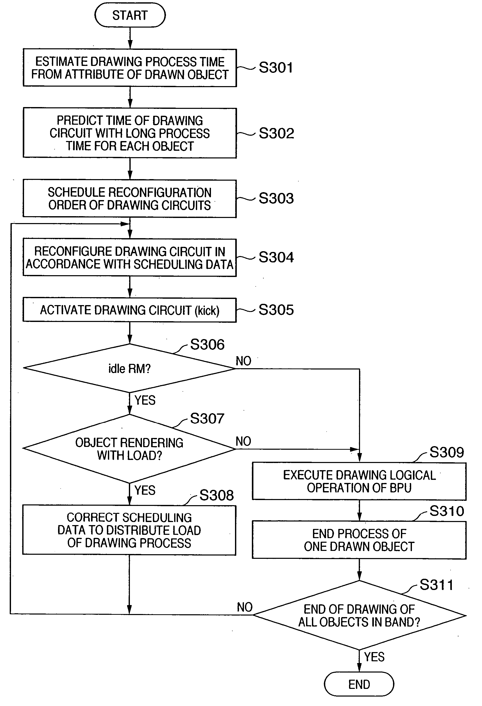
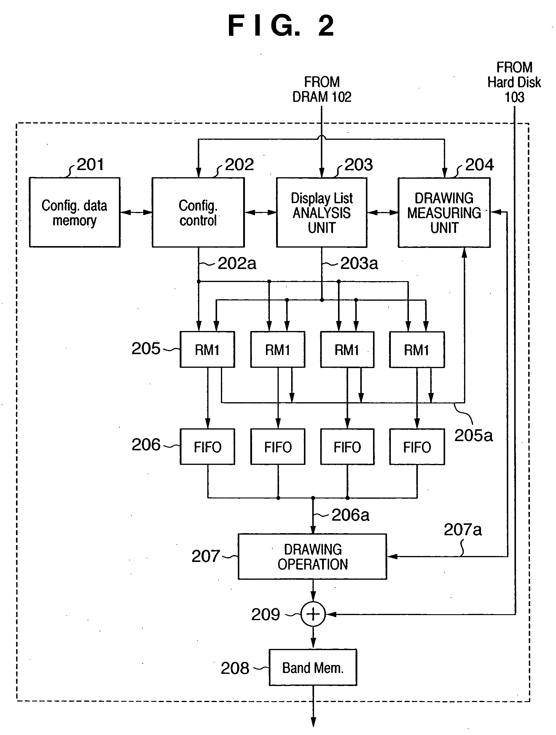
A drawing processing circuit includes a plurality of rasterizing means capable of executing rasterizing processes in parallel. Each rasterizing means includes a dynamic reconfigurable processor. Data described by a page description language is received, analyzed, and converted into intermediate data for each drawn object. Before execution of a rasterizing process, scheduling data of reconfiguration of the processor is generated by estimating the process time of each rasterizing process on the basis of the intermediate data. The plurality of rasterizing means rasterize the data to bitmap data on the basis of the intermediate data while reconfiguring the processor on the basis of the generated scheduling data. In addition, the process time of each of the plurality of rasterizing means is determined on the basis of the scheduling data. The scheduling data is corrected so as to make the process times of the plurality of rasterizing means substantially equal. With this arrangement, a method of drawing image, which reduces the waste of hardware resources and perform a high-speed drawing process, a circuit thereof, and a print control apparatus are provided.
Description
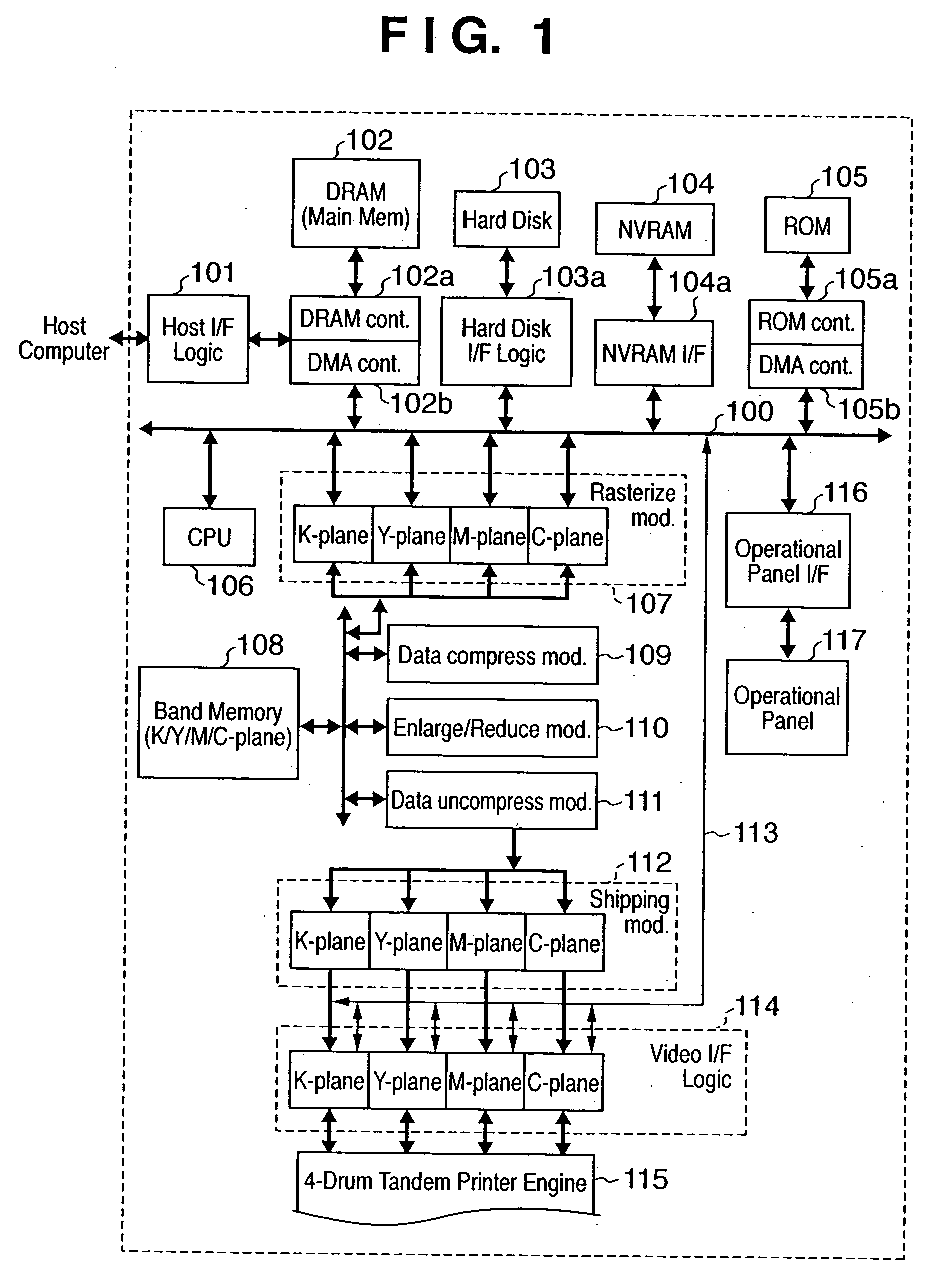
FIELD OF THE INVENTION [0001] The present invention relates to a method of drawing image, a circuit therefor, and an image output control apparatus and, more particularly, to a method of drawing image in which data as a print job described by an object description language such as PDL is received from a host computer, the data of one page is segmented into a plurality of bands, each band is converted into intermediate data, and the intermediate data is rasterized to bitmap data in accordance with the attribute of a drawn object contained in the intermediate data, a circuit therefor, and an image output control apparatus. BACKGROUND OF THE INVENTION [0002] In this specification, an image output control apparatus will be exemplified by a print control apparatus for controlling image output to a print means for printing an image. However, the present invention can also be applied to control of image output to a display means, and an apparatus therefor is also incorporated in the presen...
Claims
Login to View More Application Information
Patent Timeline
 Patent Type & AuthorityApplications(United States)
IPC IPC(8): G06F3/12
CPCG06F3/1204G06F3/1211G06F3/1285G06F3/126G06F3/1284G06F3/1245
InventorITO, NOBUYASUTACHIKAWA, TOMOHIRO
OwnerCANON KK