High performance rear-projection screen

Inactive Publication Date: 2006-03-23
REFLEXITE
View PDF21 Cites 66 Cited by
  • Summary
  • Abstract
  • Description
  • Claims
  • Application Information

AI Technical Summary

Benefits of technology

[0004] A rear-projection screen is provided in accordance with one embodiment that includes a substrate including a first side and a second side, lenticular lenses or an array of microlenses disposed on the first side of the substrate, and an opaque layer d

Problems solved by technology

Absorbing most of the front light, while at the same time maximizing the transmittance of the light projected onto the screen from th

Method used


Image

  • High performance rear-projection screen
  • High performance rear-projection screen
  • High performance rear-projection screen

Examples


Embodiment Construction

[0023] A description of various embodiments of the invention follows.

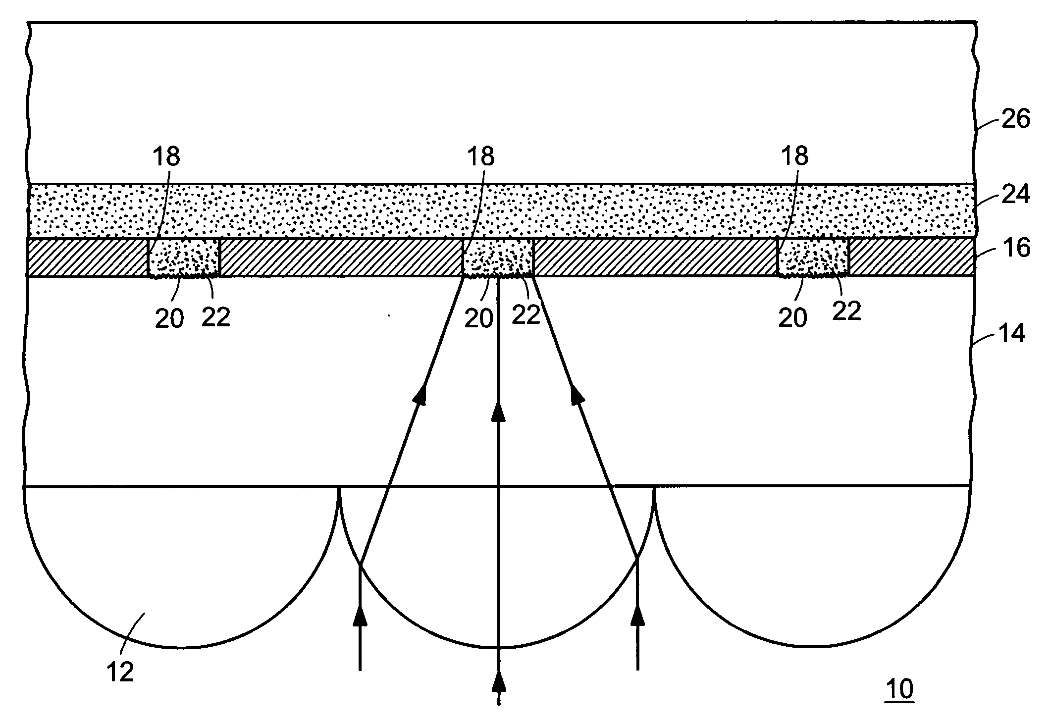
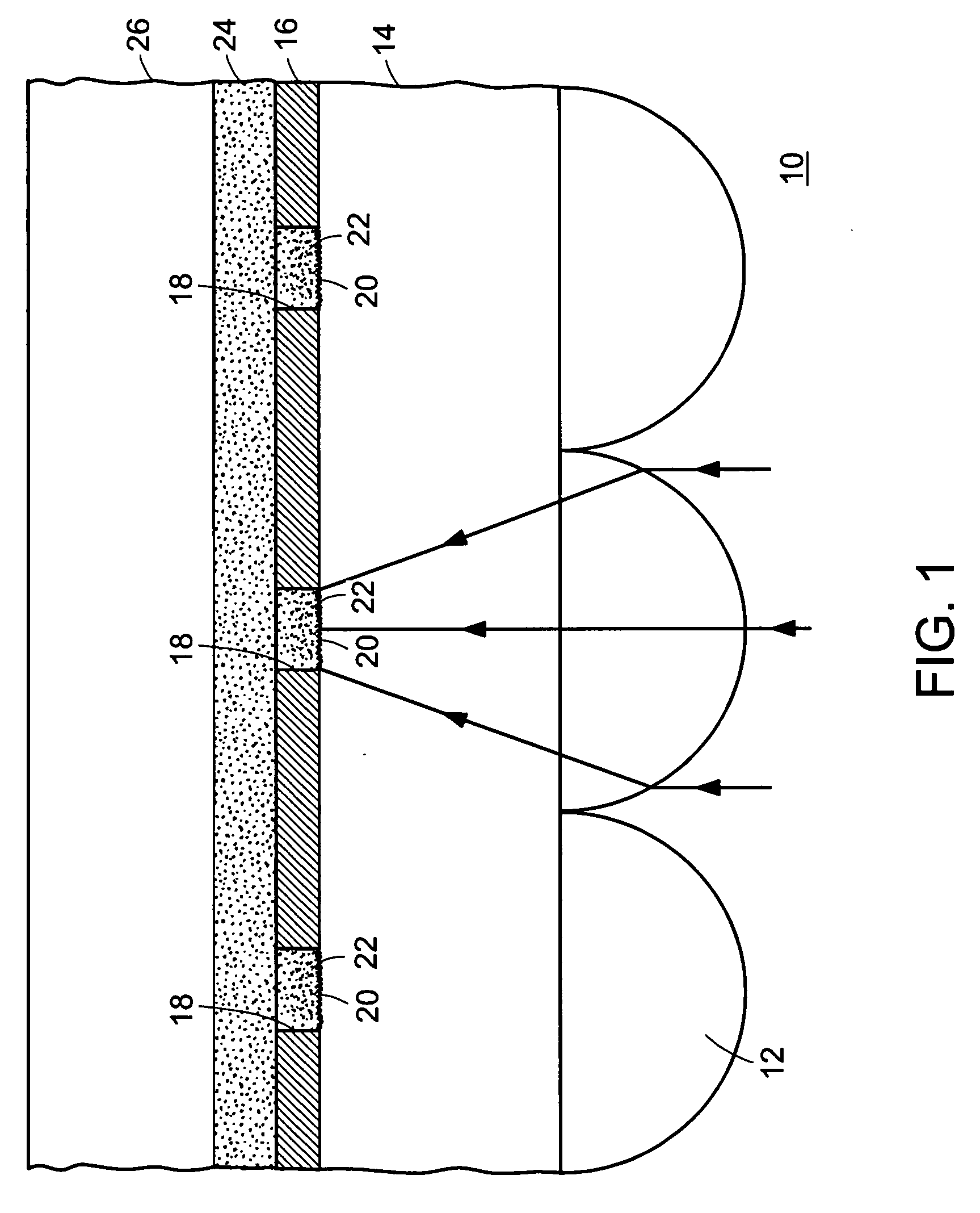
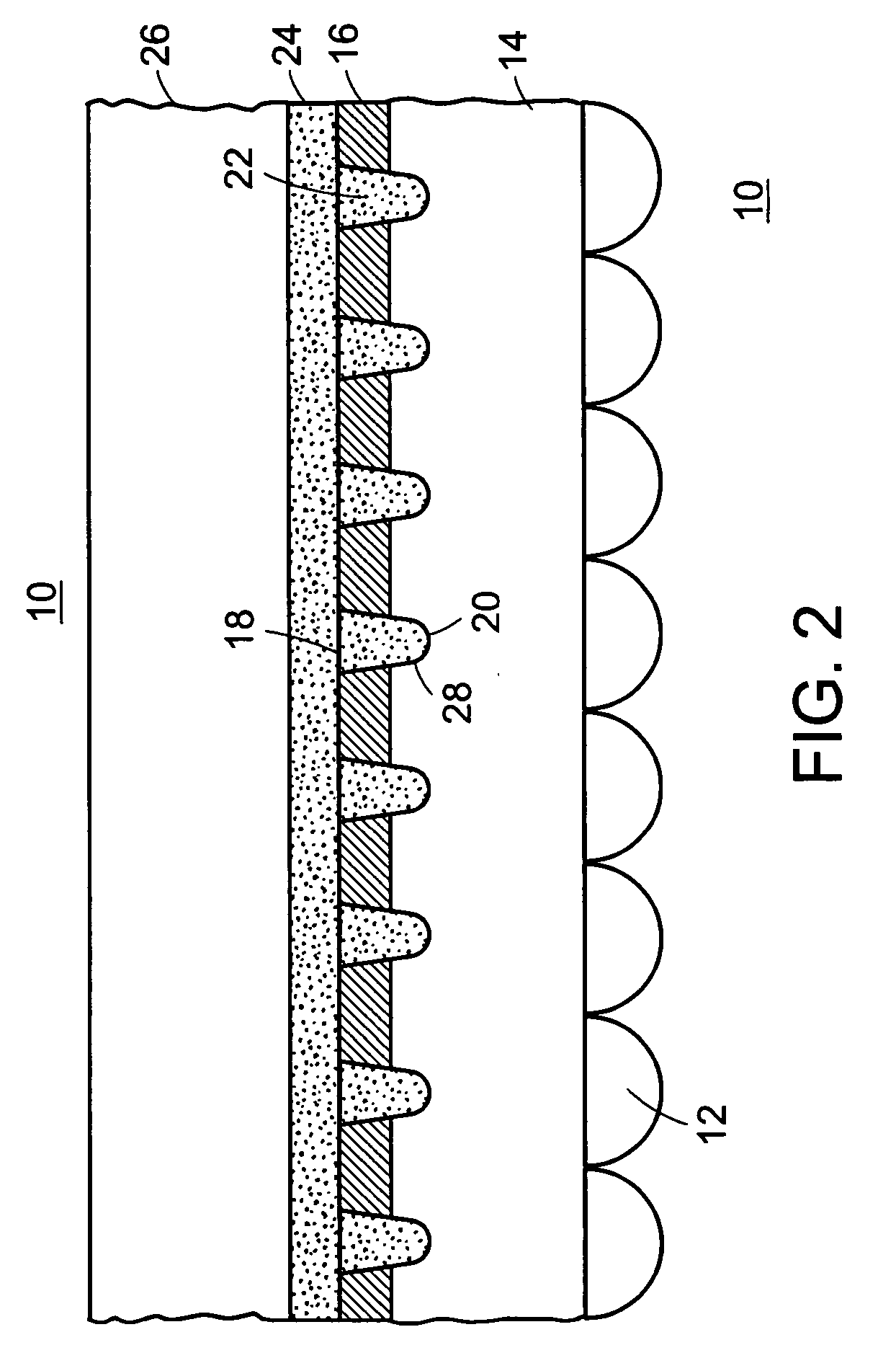
[0024]FIG. 1 is a cross-sectional view of an embodiment of a rear-projection screen 10 that has been constructed in accordance with principles of the present invention. Lenses 12, that can be for example, elliptical, circular, or circular-linear approximation-shaped, arranged in a one-dimensional lenticular array or two-dimensional array, are provided on a first side of a substrate 14. In one embodiment, the lenses 12 are cast on the substrate 14, which can have a thickness of about 0.15 mm. The substrate 14 should be substantially transparent and can include polyethylene terephthalate (PET), polycarbonate, or other suitable materials.

[0025] An opaque layer 16 is provided on the opposite or second side of the substrate 14. The opaque layer should be made as thin as possible, but not so thin that it becomes transmissive to light. In a particular embodiment, the opaque layer 16 has a thickness between about 10 to 3...


PUM


Abstract

A rear-projection screen and a method for forming same are provided. The screen can include a substrate including a first side and a second side, apertures disposed on the first side of the substrate, and an opaque layer disposed on the second side of the substrate. In a particular embodiment, the opaque layer includes a plurality of apertures therethrough. A surface relief diffuser can be provided in the substrate at the plurality of apertures. A bulk diffuser can be provided at the plurality of apertures to diffuse the projected image. A cover can be attached to the opaque layer, for example, with an adhesive. An overlayer can be provided on the opaque layer for providing deep apertures that can be filled with bulk diffuser to further diffuse the projected image. The overlayer disposed on the opaque layer can include a light-absorbing material in and/or on the overlayer.

Description

BACKGROUND OF THE INVENTION [0001] Rear-projection screens are utilized in various types of equipment, such as projection-based radar displays, televisions, flight simulators, avionic displays, traffic control lights, microfilm readers, video games, projection-based video monitors, and rear-projection film media displays for generating a user-viewable display. In such applications, an image source located behind the screen projects light forward along a projection axis toward the screen to form an image at the plane of the screen which is distributed to viewers on the front side of the screen. [0002] Where multiple viewers are present, such viewers are typically positioned horizontally, and distribution of light through a large horizontal angle is desirable. This is particularly true in rear-projection televisions, where multiple viewers are generally present and seated throughout a relatively wide horizontal angle relative to the screen. Since the viewers are not generally spread i...

Claims


Application Information

Patent Timeline
IPC IPC(8): G03B21/60
CPCG03B21/625
Inventor MUNRO, JAMES F.MULLEN, PATRICK W.
Owner REFLEXITE
Why Eureka
Try Eureka