Cooling garment having phase change material in its extremity portions

a technology of extremity portion and cooling garment, which is applied in the field of cooling garments, can solve the problems of limited body self-cooling mechanism, effective cooling of the body, and replenishment of body fluids, so as to facilitate at least one or reactivation and replacement, and facilitate at least one of reactivation and replacement.

Inactive Publication Date: 2006-03-23
CREATEC CONSULTING
View PDF23 Cites 55 Cited by
  • Summary
  • Abstract
  • Description
  • Claims
  • Application Information

AI Technical Summary

Benefits of technology

[0015] In yet another aspect, there is provided a cooling garment comprising a phase change material and at least one of a shirt portion and a pants portion. The shirt portion has left and right arm portions removably attached to a torso portion. The phase change material is disposed in the left and right arm portions, and the left and right arm portions are removable from the torso portion to faci...

Problems solved by technology

However, the body's self-cooling mechanism is limited in at least a couple of ways.
First, it will only effectively cool the body at or below a certain ambient temperature and at humidity well under 100%.
Second, body fluids must be replenished to sustain the self-cooling mechanism.
Heat stress may result in various harmful physiological effects on the body's functions.
If heat stress is combined with hard and stressful work, it may develop into a life-threatening condition known as heat stroke.
The use of cooling garments may be problematic due to the high extra weight for some applications, difficulties with arranging a good heat transport from the body to the garment, and the time and effort needed to reactivate the garment after use, e.g., half an hour in ice-cold water.
In addition, if ice is used for cooling, the vasoconstriction effect by restricting the blood flow counteracts the cooling capacity of ice.
The problem is that to be effective, high airflow of 200-300 liters/minute is needed, and the ambient air ...

Method used


Image

  • Cooling garment having phase change material in its extremity portions
  • Cooling garment having phase change material in its extremity portions
  • Cooling garment having phase change material in its extremity portions

Examples


Embodiment Construction

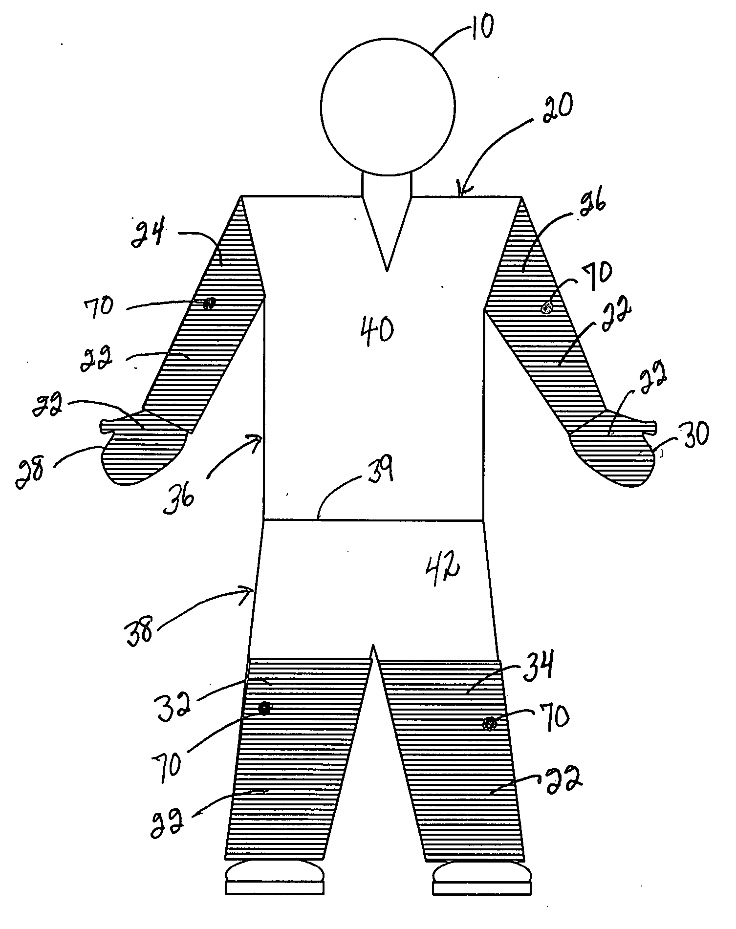
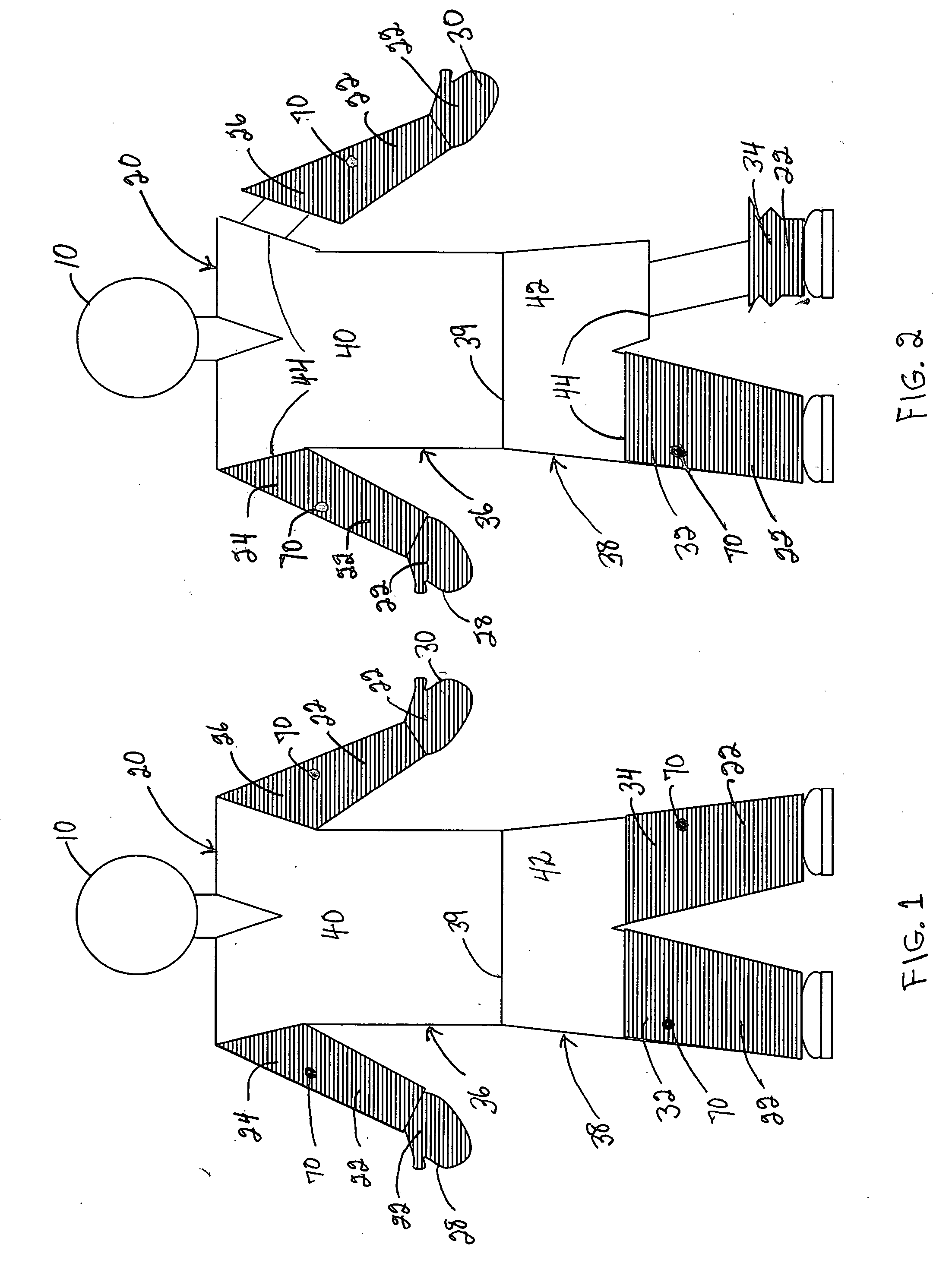
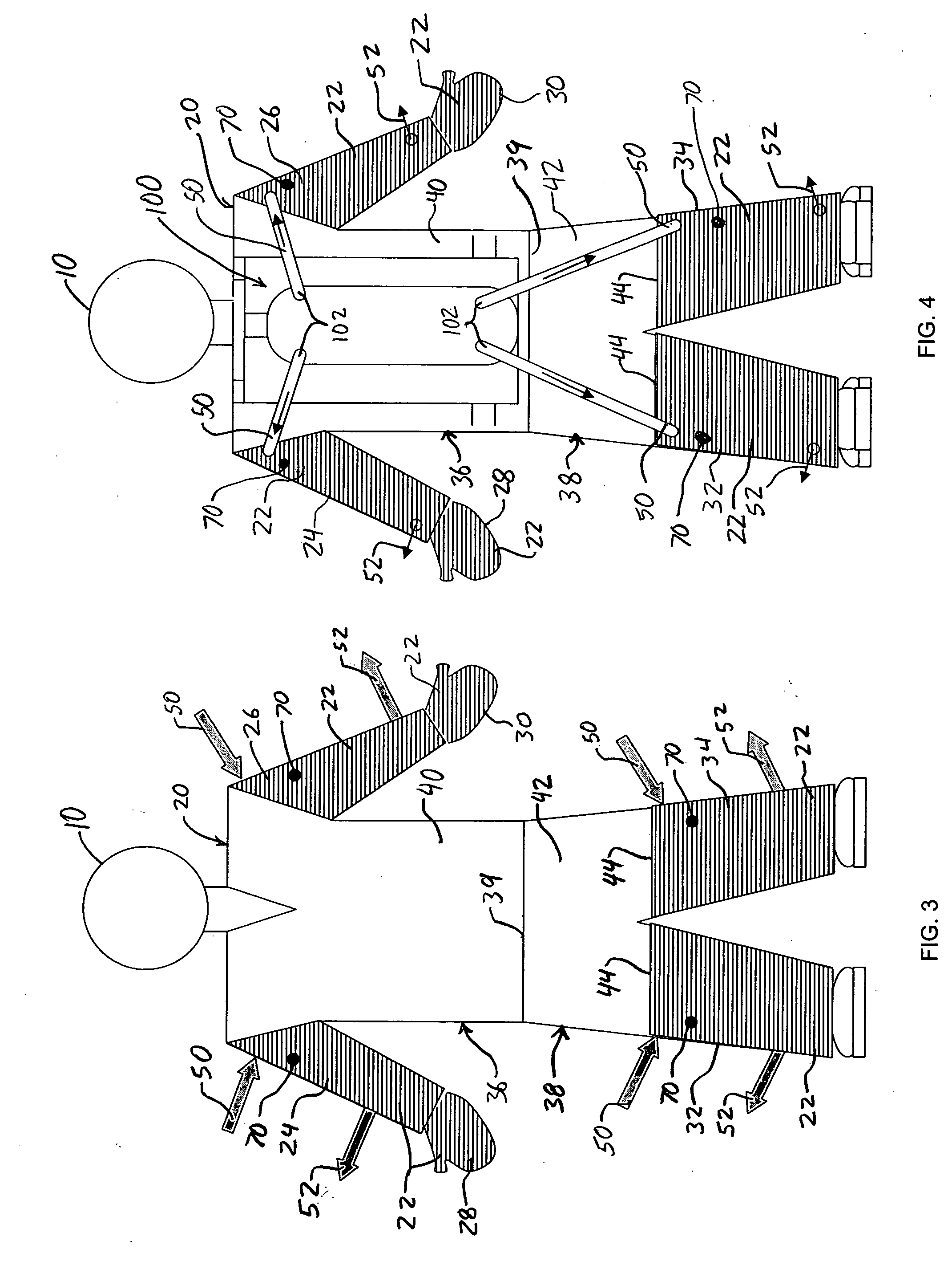
[0024]FIG. 1 depicts a front view of a worker 10 wearing a cooling garment 20 having phase change material (PCM) 22 (indicated by horizontal hatching) in its extremity portions, e.g., right and left arms 24, 26, right and left gloves 28, 30, and right and left legs 32, 34. The PCM 22 may be secured within the garment using any convenient means. For example, the PCM 22 may be attached (e.g., sewn, molded, etc.) to the inner portion of the garment such that the PCM 22 is in direct contact to the skin of the worker 10. Alternatively, the PCM 22 may be disposed between two or more layers of material, with the material disposed between the PCM 22 and the worker 10 transferring heat between the worker 10 and the PCM 22. PCM 22 typically will be incorporated in small pads adjacent a wearer's hands, arms, legs, or other places on the body that have good circulation and therefore good heat transfer ability. Typically, the pads will be adapted to make good skin contact with a wearer to increa...


PUM


Abstract

A cooling garment comprises a phase change material and at least one of: a shirt portion and a pants portion. The shirt portion has left and right arm portions attached to a torso portion, with the phase change material being disposed in the left and right arm portions. The pants portion has left and right leg portions, with the phase change material being disposed in the left and right leg portions. The arm and leg portions may be removable to facilitate reactivation and/or replacement of the phase change material, and the cooling garment may include a sensor configured to indicate a cooling capacity of the phase change material. A portable container having a reactivation substance stored therein may be provided to reactivate the phase change material. In one embodiment, the portable container is part of a self-contained breathing apparatus. In another embodiment, the phase change material is submerged in the reactivation substance in the container.

Description

CROSS-REFERENCE TO RELATED APPLICATIONS [0001] This application claims the benefit of U.S. Provisional Patent Application No. 60 / 585,519 filed Jul. 2, 2004, which is incorporated by reference herein in its entirety.BACKGROUND [0002] (1) Field of the Invention [0003] The present invention generally relates to cooling garments for preventing heat-related illnesses. In particular, the present invention is directed to a cooling garment that includes phase change materials (PCM) in its extremity portions, e.g., sleeves, legs, and gloves. [0004] (2) Description of the Related Art [0005] Generally speaking, the human body can tolerate cold environments rather well, but is very sensitive to hot environments. The body has a self-cooling mechanism in the form of evaporation of sweat. However, the body's self-cooling mechanism is limited in at least a couple of ways. First, it will only effectively cool the body at or below a certain ambient temperature and at humidity well under 100%. Second,...

Claims


Application Information

Patent Timeline
IPC IPC(8): A61F7/00
CPCA61F7/02A61F2007/0031A61F2007/0292A61F2007/0095A61F2007/0233A61F2007/0041
Inventor ALMQVIST, HANS O.
Owner CREATEC CONSULTING
Why Eureka
Try Eureka