
Foundation module

a technology of foundation module and module, applied in the field of foundation module, can solve problems such as unstable apparatus, and achieve the effect of increasing the stability of apparatus

Inactive Publication Date: 2006-03-30
CORETRONIC
View PDF9 Cites 6 Cited by
  • Summary
  • Abstract
  • Description
  • Claims
  • Application Information

AI Technical Summary

Benefits of technology

[0005] To solve the above-mentioned problem, an objective of the invention is to provide a foundation module to increase the stability of apparatuses such as projectors.
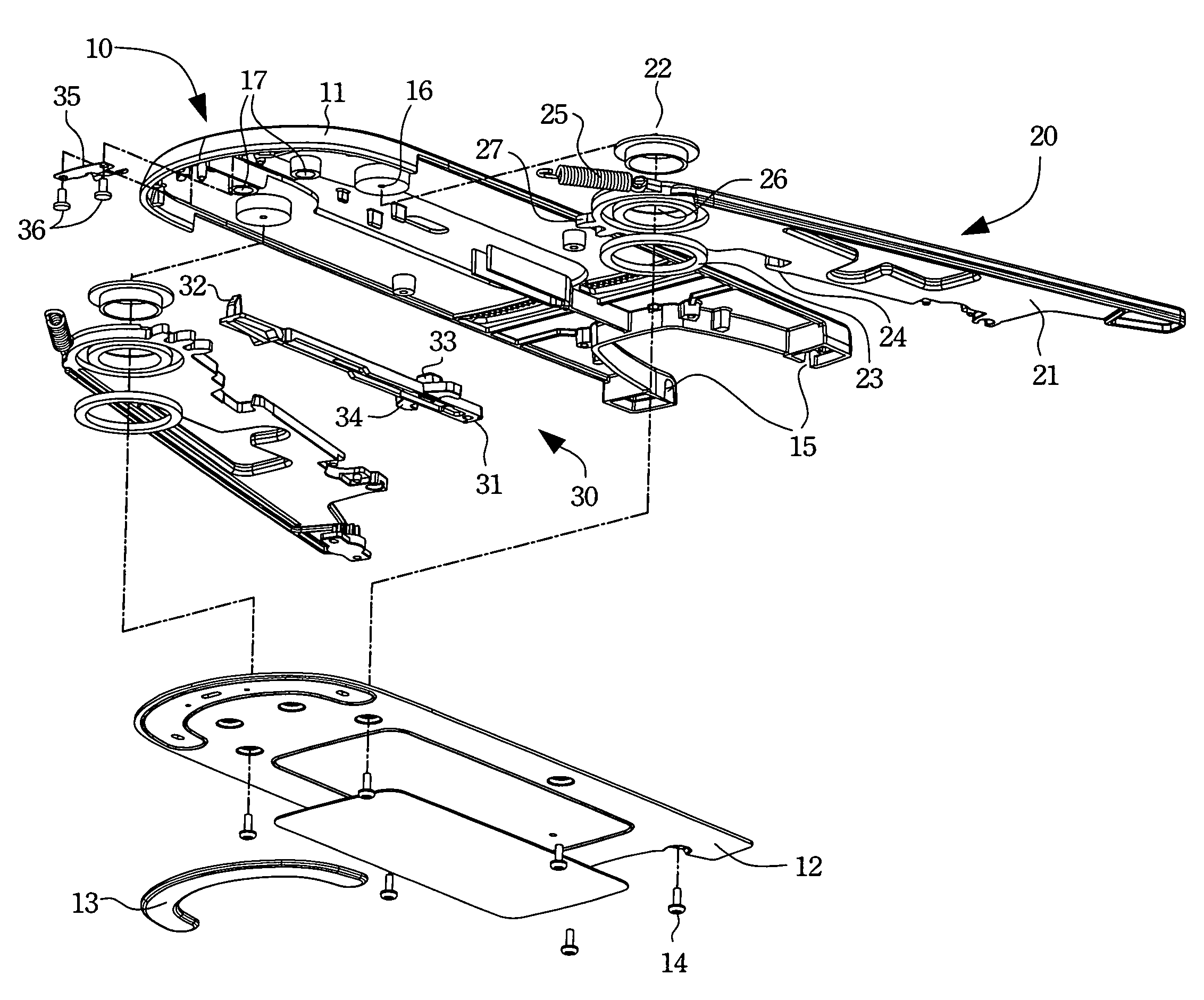
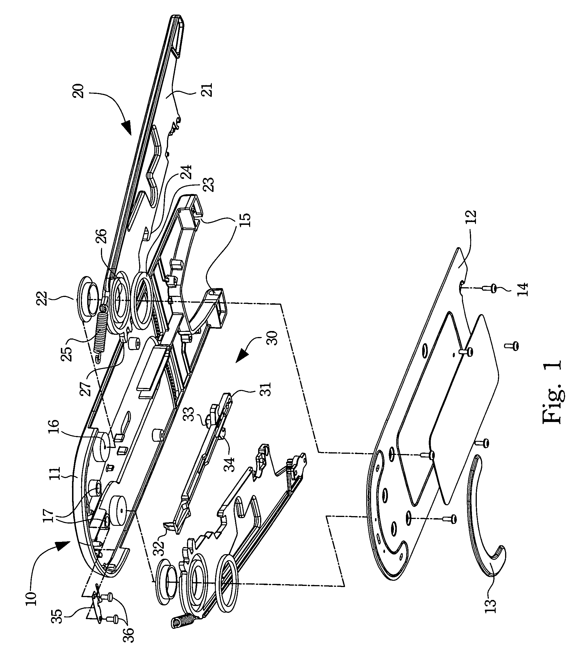
[0006] The disclosed foundation module includes a base, a wing support, and a linkage. The base is pivotally installed on one side of an apparatus, such as a projector, and rotates about the pivotal point to adjust the projecting angle between the apparatus and the base plane. The wing support is installed on the inner side of the base and can horizontally extend out. The linkage is at the center of the base. The wing support can automatically extend out of the base to support the apparatus with the operation of the linkage. Therefore, when using the apparatus, the wing support is extended out automatically or manually to effectively increase the base area for the apparatus to work more stable. The wing support can be stored in the base to save the space of the apparatus.

Problems solved by technology

Therefore, if they also use tripods, the apparatus may become unstable.
This may result in damages due to stumbling.

Method used


Image

  • Foundation module
  • Foundation module
  • Foundation module

Examples


Embodiment Construction

[0016] The present invention will be apparent from the following detailed description, which proceeds with reference to the accompanying drawings, wherein the same references relate to the same elements.

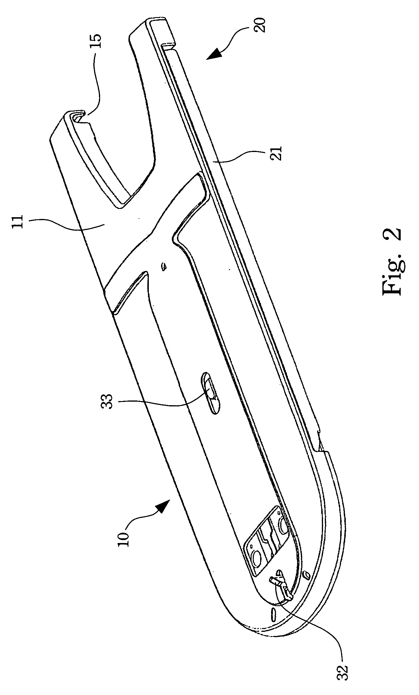
[0017] As shown in FIGS. 1, 2, and 3, the disclosed foundation module includes a base 10, a set of wing support 20 inside the base 10 and extensible horizontally along the side of the base 10, and a linkage 30 at the center of the base 10.

[0018] The base 10 has a part with similar area and shape to the apparatus 40, such as a projector. The base 10 further contains a base top cover 11, a base bottom cover 12, a wing axis 16, and an apparatus mounting hole 15. The base top cover 11 and the base bottom cover 12 can be fixed. Once they are fixed, the space formed therein can accommodate the wing support 20 and the linkage 30. The bottom surface of the base bottom cover 12 contains at least a stop pad 13 to increase the stability. The apparatus mounting hole 15 is located on one side o...


PUM


Abstract

A foundation module is described. The foundation module is utilized in an apparatus, e.g. a projector or the like, that requires a stable working condition. The foundation module includes a base, a wing support, and a linkage. The wing support horizontally extends out of the base to support the apparatus with the operation of the linkage. The wing support can automatically extend from the base to increase the supporting area for the apparatus to work more stable when the apparatus is operating. The wing support can be stored in the base to save the space of the apparatus.

Description

BACKGROUND OF THE INVENTION [0001] 1. Field of Invention [0002] The invention relates to a foundation module and, in particular, to a foundation that can extend out automatically. [0003] 2. Related Art [0004] Influenced by the advances in technology and environmental protection, various devices become smaller than before. Take a projector as an example. New small portable models with higher resolutions, brightness, and projection areas have been developed, in comparison with the large standing one years ago. There are also vertical standing models that do not occupy too much planar space than the conventional horizontal ones. Traditionally, most of the horizontal projectors use the three-point support, where one of them can be raised or lowered to adjust the projecting angle of the projector. The other two pods are used to adjust the level of the machine. The vertical models have smaller placing areas, with higher centers of gravity. Therefore, if they also use tripods, the apparatu...

Claims


Application Information

Patent Timeline
Patent Type & Authority Applications(United States)
IPC IPC(8): E05C5/00
CPCF16M11/04F16M11/041F16M11/10G03B21/14F16M2200/041F16M2200/08F16M11/22G03B21/145
Inventor CHANG, TAI-LI
Owner CORETRONIC
Learn More