
Full-color electrochromic display with stacked in cell monochromic electrochromes

a full-color, electrochromic display technology, applied in the direction of instruments, discharge tubes luminescnet screens, static indicating devices, etc., can solve the problems of low switching speed and high power consumption of electrochromic display technologies commercially available today, and the generation of color with respect to electrochromic displays

Inactive Publication Date: 2006-03-30
KONINKLIJKE PHILIPS ELECTRONICS NV
View PDF12 Cites 48 Cited by
  • Summary
  • Abstract
  • Description
  • Claims
  • Application Information

AI Technical Summary

Benefits of technology

[0032] Thus, while there have been shown and described and pointed out fundamental novel features of the invention as applied to a preferred embodiment thereof, it will be understood that various omissions and substitutions and changes in the form and details of the devices illustrated, and in their operation, may be made by those skilled in the art without departing from the spirit of the invention. For example, it is expressly intended that all combinations of those elements and / or method steps which perform substantially the same function in substantially the same way to achieve the same results are within the scope of the invention. Moreover, it should be recognized that structures and / or elements and / or method steps shown and / or described in connection with any disclosed form or embodiment of the invention may be incorporated in any other disclosed or described or suggested form or embodiment as a general matter of design choice. It is the intention, therefore, to be limited only as indicated by the scope of the claims appended hereto.

Problems solved by technology

However, the slow switching speed and high power consumption of the electrochromic display technologies commercially available today do not meet the needs of the display market.
However, one of the remaining key issues with respect to electrochromic displays is the generation of color.

Method used


Image

  • Full-color electrochromic display with stacked in cell monochromic electrochromes
  • Full-color electrochromic display with stacked in cell monochromic electrochromes
  • Full-color electrochromic display with stacked in cell monochromic electrochromes

Examples


Embodiment Construction

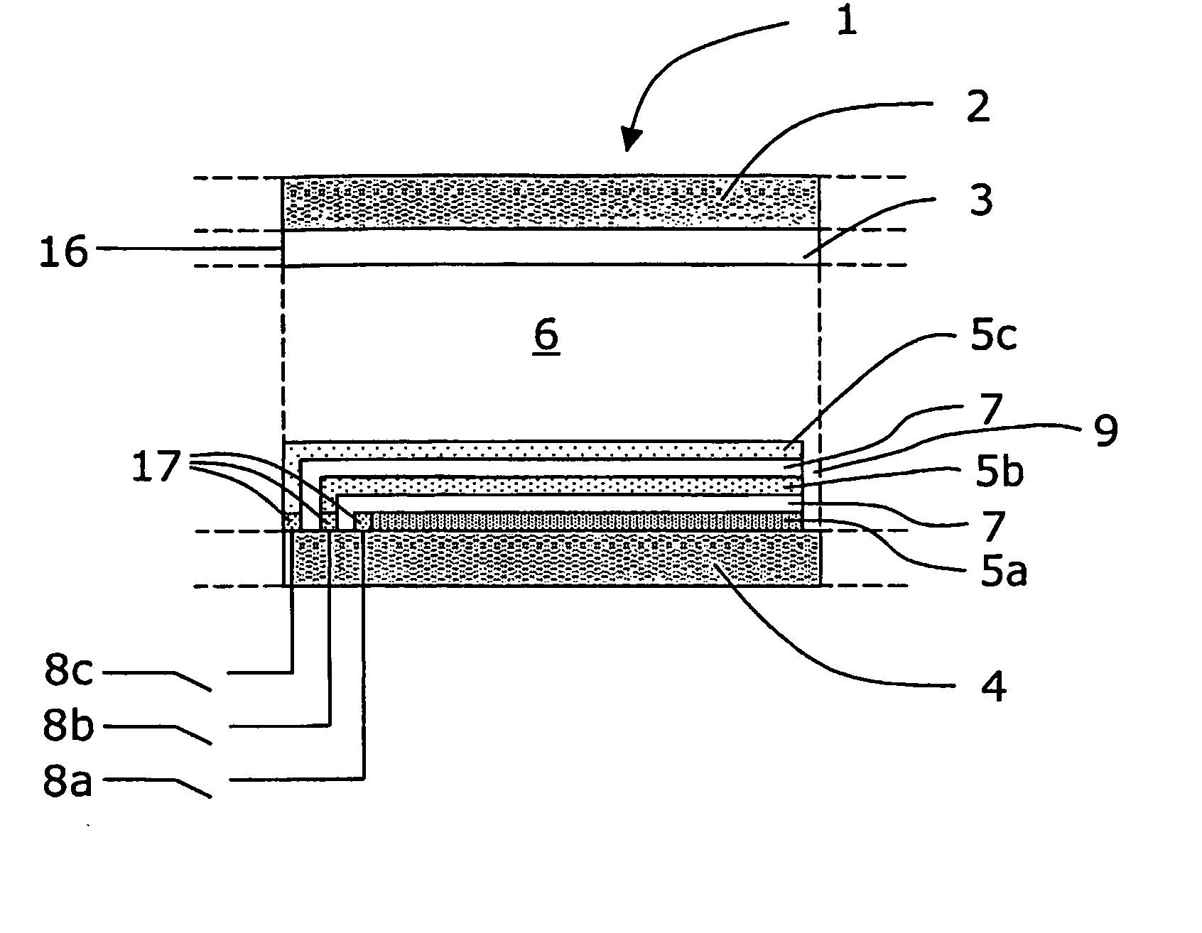
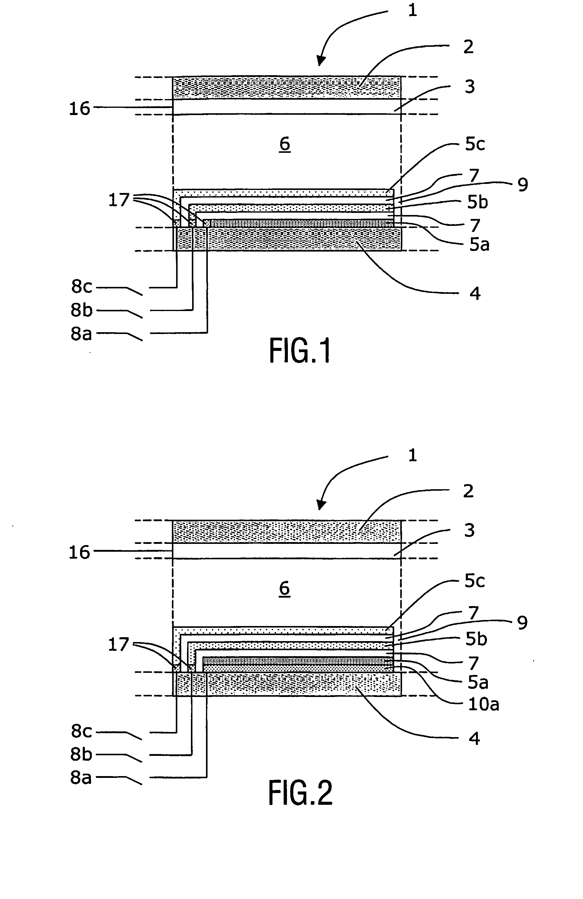
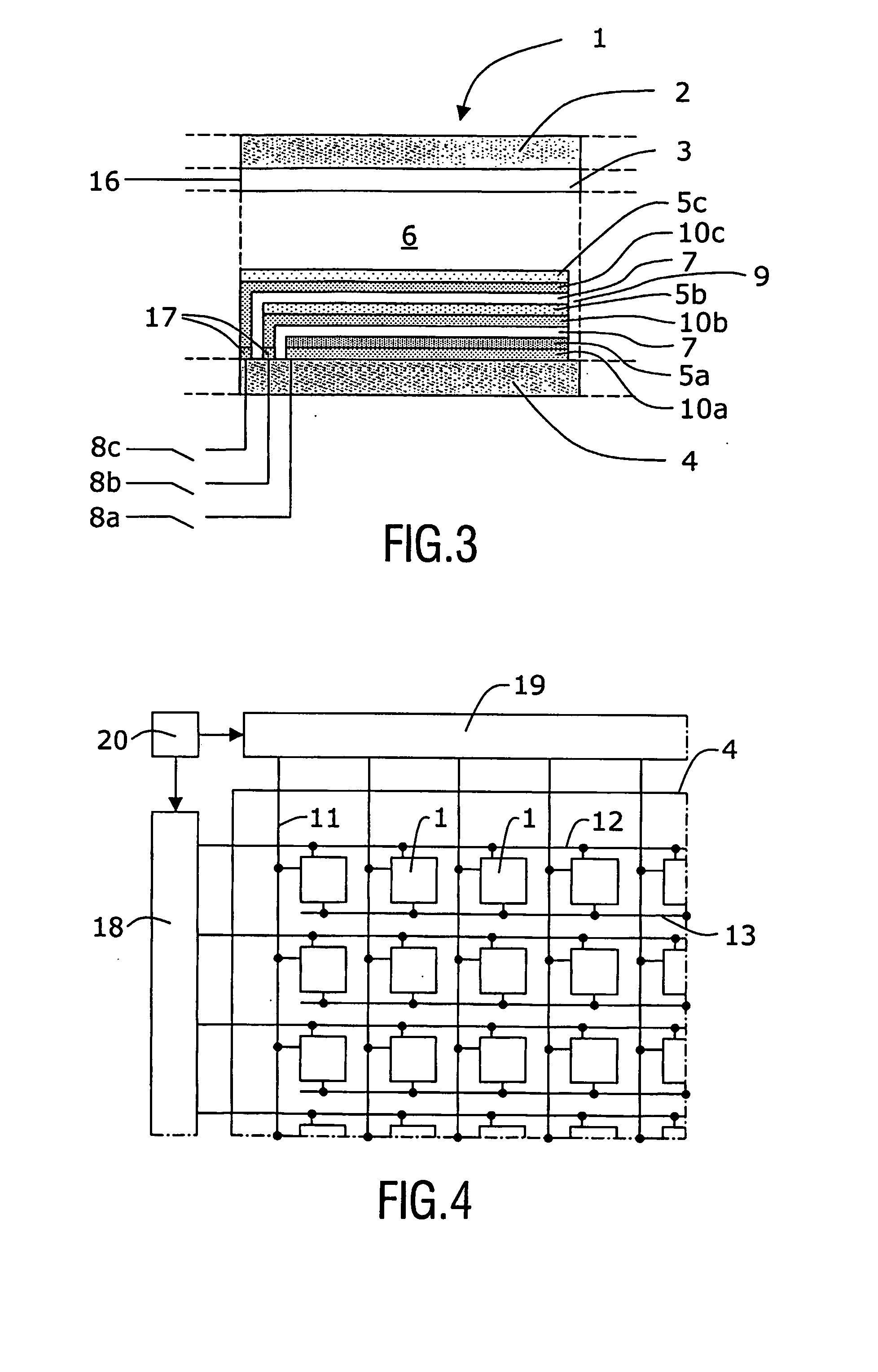
[0019]FIG. 1 shows a schematic cross sectional view of a pixel 1 of an electrochromic display according to a first embodiment. Each pixel of the electrochromic display is independently addressable and can be separated from other pixels either electrically or physically, in order to avoid cross-talk between pixels. The pixel 1 comprises: a first substrate 2, which is preferably transparent and made of a material such as a glass or from a plastic plate; a conductive counter-electrode 3 associated with said first substrate 2; a second substrate 4, which can be reflective or transparent; a stack of electrochromic-layers 5a, 5b, 5c associated with said second substrate 4; a transparent electrolytic material 6 disposed between said counter-electrode 3 and said stack of electrochromic-layers 5a, 5b, 5c and which is in contact with said counter-electrode 3 and the adjacent electrochromic-layer 5c in said stack of electrochromic-layers 5a, 5b, 5c. The electrochromic-layers 5a, 5b, 5c are ind...


PUM


Abstract

A display device comprising a plurality of independently addressable pixels (1) comprising: a first substrate (2); a counter-electrode second substrate (4); a stack associated with said second substrate (4); an electrolyte (6) disposed between said counter-electrode (3) and said stack of electrochromic layers (5a, 5b, 5c). Said electrochromic layers (5a, 5b, 5c) are each independently addressable for switching operation; and separated from each other by layers of an electrolyte (7). A driving method for operating said pixel (1) comprises the steps of providing at least one power line (8) which is selectively connectable to an electrochromic layer (5) or a working electrode (10) associated with said electrochromic layer (5); selectively applying to said power line (8) a bleaching or coloring voltage; addressing the electrochromic layer (5) which is to be bleached or colored; connecting said power line (8) to said addressed electrochromic layer (5); retaining the connection of said power line (8) during a hold period; and disconnecting said power line (8).

Description

FIELD OF THE INVENTION [0001] The present patent application relates to the field of electrochromic display devices, and particularly to an apparatus for providing full-color operation to such display devices and a drive method therefor. More specifically, the present patent application relates to an efficient system for providing full-color operation for each pixel cell of electrochromic display devices. BACKGROUND OF THE INVENTION [0002] Recently electrochromic display devices have been studied as candidates for electronic paper type of displays. However, the slow switching speed and high power consumption of the electrochromic display technologies commercially available today do not meet the needs of the display market. Lately the trend has been towards the use of nano-materials, such as chemically modified nano-structured mesoporous films, for improving performance. Use of such materials has shown promising results. However, one of the remaining key issues with respect to electr...

Claims


Application Information

Patent Timeline
IPC IPC(8): G02F1/15G02F1/155G09G3/19G09G3/20G09G3/38
CPCG02F1/15G02F1/155G09G2340/16G09G3/38G09G2300/0809G02F2001/1515G02F1/15165G02F1/163
Inventor JAGT, HENDRIK JOHANNES BOUDEWIJNWILLARD, NICOLAAS PETRUSJOHNSON, MARK THOMAS
Owner KONINKLIJKE PHILIPS ELECTRONICS NV
Learn More